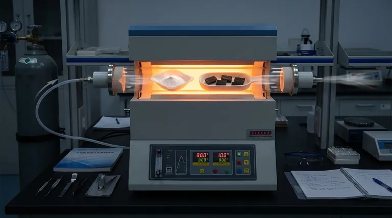
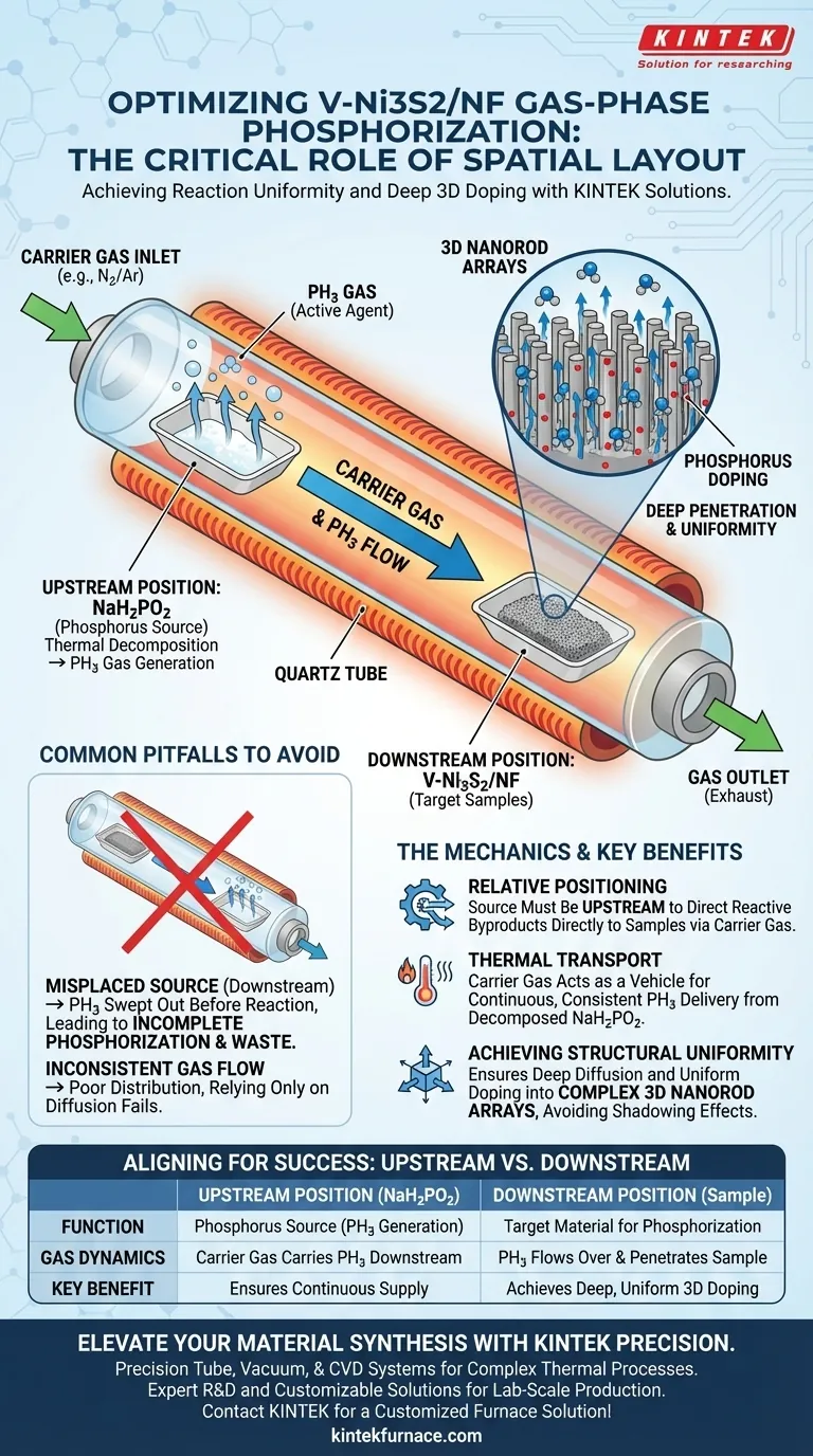
The spatial layout is critical for achieving reaction uniformity. Specifically, placing sodium hypophosphite (NaH2PO2) at the upstream position of the porcelain boat is necessary to direct the thermal decomposition products correctly. This arrangement allows the carrier gas to transport the resulting phosphine (PH3) gas downstream, ensuring it flows directly over the V-Ni3S2/NF precursors.
The upstream placement of the phosphorus source is the defining factor that guarantees deep penetration and uniform distribution of phosphorus atoms throughout the complex three-dimensional nanorod arrays.
The Mechanics of Gas-Phase Phosphorization
The Role of Relative Positioning
The success of the annealing process relies on the relationship between the gas flow direction and the material placement.
Because the carrier gas flows from the inlet to the outlet, the source material (NaH2PO2) must be placed upstream relative to the target sample.
This ensures that as the source decomposes, the reactive byproducts are pushed immediately toward the metal precursors rather than away from them.
Thermal Decomposition and Transport
During the tube furnace annealing process, sodium hypophosphite undergoes thermal decomposition to produce phosphine (PH3) gas.
This gas is the active phosphorizing agent.
By positioning the source upstream, the carrier gas acts as a transport vehicle, delivering a continuous and consistent stream of PH3 to the V-Ni3S2/NF samples located downstream.
Achieving Structural Uniformity
Deep Penetration
The primary goal of this spatial layout is to facilitate deep penetration of the reactants.
Simply exposing the surface is insufficient for high-performance materials; the phosphorous must integrate thoroughly into the material.
The directed flow of PH3 ensures that phosphorus atoms can diffuse deeply into the substrate rather than merely coating the exterior.
Uniformity in 3D Arrays
The V-Ni3S2/NF samples are characterized by three-dimensional nanorod arrays.
These complex geometries are difficult to dope uniformly without a consistent gas flow.
The upstream configuration ensures that the phosphine gas permeates the entire array structure, preventing uneven doping or "shadowing" effects where parts of the nanorods remain unreacted.
Common Pitfalls to Avoid
Misplaced Source Material
If the sodium hypophosphite is placed downstream or parallel to the samples, the carrier gas will sweep the PH3 gas out of the furnace before it reacts.
This leads to incomplete phosphorization and significant waste of the precursor material.
Inconsistent Gas Flow
While placement is key, the carrier gas must be flowing to facilitate the transport.
Relying solely on diffusion without the carrier gas transport provided by the upstream setup would likely result in poor distribution.
The "upstream" logic fails if the carrier gas is not effectively moving the decomposition products across the sample zone.
Making the Right Choice for Your Goal
To ensure the successful synthesis of V-Ni3S2/NF, you must align your setup with the flow dynamics of your furnace.
- If your primary focus is reaction completeness: Ensure the NaH2PO2 is strictly upstream so the full volume of generated PH3 passes over the sample.
- If your primary focus is structural integrity: Use this layout to guarantee that the 3D nanorod arrays receive uniform doping without gradient defects.
Correct spatial alignment transforms a simple annealing process into a precision doping technique for complex nanostructures.
Summary Table:
| Factor | Upstream Position (NaH2PO2) | Downstream Position (Sample) |
|---|---|---|
| Function | Phosphorus source (PH3 generation) | Target material for phosphorization |
| Gas Dynamics | Carrier gas carries PH3 downstream | PH3 gas flows over and penetrates sample |
| Key Benefit | Ensures continuous supply of reactant | Achieves deep, uniform 3D doping |
| Risk of Error | If downstream, PH3 is lost to exhaust | If upstream, incomplete reaction occurs |
Elevate Your Material Synthesis with KINTEK Precision
Achieving uniform gas-phase phosphorization requires more than just correct spatial layout; it demands a furnace with precise temperature control and stable gas flow. KINTEK provides industry-leading Tube, Vacuum, and CVD systems designed for complex thermal decomposition processes like NaH2PO2-based phosphorization.
Backed by expert R&D and manufacturing, our systems are customizable to meet the unique needs of lab-scale 3D nanorod array production. Ensure deep penetration and structural integrity in your samples every time.
Ready to optimize your high-temperature lab processes? Contact KINTEK today for a customized furnace solution!
Visual Guide
References
- Kyeongseok Min, Sung‐Hyeon Baeck. Unveiling the Role of V and P Dual‐Doping in Ni<sub>3</sub>S<sub>2</sub> Nanorods: Enhancing Bifunctional Electrocatalytic Activities for Anion Exchange Membrane Water Electrolysis. DOI: 10.1002/sstr.202500217
This article is also based on technical information from Kintek Furnace Knowledge Base .
Related Products
- Vacuum Dental Porcelain Sintering Furnace for Dental Laboratories
- Ultra High Vacuum CF Observation Window Flange with High Borosilicate Glass Sight Glass
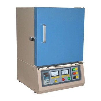
- High Temperature Muffle Oven Furnace for Laboratory Debinding and Pre Sintering
- Ultra High Vacuum Observation Window Stainless Steel Flange Sapphire Glass Sight Glass for KF
- Chairside Dental Porcelain Zirconia Sintering Furnace with Transformer for Ceramic Restorations
People Also Ask
- What economic benefits does using a dental sintering furnace offer? Boost Profits with Faster, Automated Dental Lab Workflows
- How does the sintering process work in dental furnaces? Achieve Precise Dental Restoration Transformations
- What are the cooling requirements for ceramics in the Fast Slow Dental Sintering Furnace? Ensure Crack-Free Restorations
- What is the purpose of dental sintering furnaces? Transform Zirconia into Durable, High-Quality Dental Restorations
- What is a dental sintering furnace and what is its purpose? Achieve High-Strength Dental Restorations