The geometric structure of a graphite heating element is the decisive factor in shaping the electric and thermal fields within a vacuum furnace. While the material’s conductivity plays a role, the physical design—specifically the ratio of surface area to power—determines whether the heat radiates evenly or creates damaging localized hotspots.
Core Takeaway Shifting from tubular to plate-shaped geometries increases the available radiation surface area. This significantly reduces surface heat flux density, eliminating radial temperature variances and ensuring the uniform thermal environment required for sensitive material processing.
The Physics of Heater Geometry
Surface Area and Heat Flux
The relationship between geometry and thermal distribution is governed by surface heat flux density.
This metric is defined by how much power is emitted per unit of surface area. A design with a limited surface area forces the element to operate at a higher intensity to deliver the same total energy.
The Problem with Tubular Heaters
Traditional tubular heaters typically feature a smaller total surface area relative to their volume.
To generate the necessary temperatures, these elements must endure high surface loads. This concentration of energy frequently results in local hot spots.
Consequences of Concentrated Heat
When heat is concentrated in small areas, it creates steep radial temperature differences.
This uneven distribution compromises the homogeneity of the heating zone, leading to inconsistent processing results across the workload.
The Plate-Shaped Advantage
Increasing Radiation Exchange
Plate-shaped heaters are designed to maximize the radiation heat exchange area.
By spreading the electrical resistance path over a wider, flatter surface, the heater can emit the same amount of energy without reaching extreme localized intensities.
Improving Thermal Uniformity
Because the surface heat flux density is lowered, the temperature reduces its peak intensity at the source.
This results in a smoother, more consistent thermal field distribution throughout the furnace chamber.
Extending Component Lifespan
Geometric optimization does not just affect the product; it protects the furnace.
Lowering the surface heat flux reduces the thermal stress on the graphite itself. This directly contributes to extending the service life of the heating components.
Critical Impact on Material Processing
Controlling the Melt Interface
In applications like silicon crystal growth, the heater’s geometry drives the temperature gradient within the melt.
Precise distribution is required to define the crystal's interface shape and manage the crystallization rate.
Preventing Structural Defects
A uniform thermal field is the primary defense against thermal stress in the growing material.
By eliminating localized heat concentrations, the correct geometric design prevents dislocation defects and ensures replicable, high-quality results.
Understanding the Trade-offs
High Intensity vs. Longevity
The primary trade-off in heater design involves the intensity of the surface load versus the longevity of the component.
The Cost of Non-Uniformity
Choosing a geometry that promotes high surface loads (like narrow tubes) may simplify design in some contexts, but it accelerates component degradation.
Conversely, maximizing surface area (plates) requires careful spatial planning but pays dividends in process consistency and heater durability.
Making the Right Choice for Your Goal
To select the correct graphite heater geometry for your specific vacuum furnace application:
- If your primary focus is Temperature Uniformity: Prioritize plate-shaped heaters to maximize radiation surface area and lower the flux density.
- If your primary focus is Component Longevity: Choose designs with low surface heat flux to reduce thermal stress and extend the service life of the graphite.
- If your primary focus is Crystal Quality: Ensure the geometry allows for precise temperature gradient control to prevent dislocation defects during crystallization.
Ultimately, the geometric design of your heater is not just a structural choice; it is the control mechanism for the thermal quality of your final product.
Summary Table:
| Feature | Tubular Heaters | Plate-Shaped Heaters |
|---|---|---|
| Surface Area | Limited/Smaller | Maximized/Larger |
| Heat Flux Density | High (Concentrated) | Low (Distributed) |
| Thermal Uniformity | Risk of Local Hotspots | High Homogeneity |
| Component Lifespan | Lower (Higher Stress) | Extended (Lower Stress) |
| Best For | Basic Heating Needs | Precise Material Processing |
Elevate Your Thermal Precision with KINTEK
Don't let uneven heat distribution compromise your materials or shorten your equipment's lifespan. Backed by expert R&D and manufacturing, KINTEK delivers high-performance Muffle, Tube, Rotary, Vacuum, and CVD systems tailored to your exact geometric and thermal requirements. Whether you are growing crystals or processing advanced ceramics, our customizable lab high-temp furnaces ensure the perfect thermal field every time.
Ready to optimize your furnace performance? Contact our technical experts today to discuss your unique heating needs!
References
- Mao Li, Hesong Li. Numerical simulation of the heating process in a vacuum sintering electric furnace and structural optimization. DOI: 10.1038/s41598-024-81843-8
This article is also based on technical information from Kintek Furnace Knowledge Base .
Related Products
- 2200 ℃ Graphite Vacuum Heat Treat Furnace
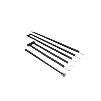
- Silicon Carbide SiC Thermal Heating Elements for Electric Furnace
- Molybdenum Vacuum Heat Treat Furnace
- Vacuum Heat Treat Furnace with Ceramic Fiber Liner
- Small Vacuum Heat Treat and Tungsten Wire Sintering Furnace
People Also Ask
- What are the advantages of using a vacuum heat treatment furnace? Achieve Superior Material Quality and Control
- How does a vacuum heat treat furnace work? Achieve Pristine, High-Performance Results
- How does a vacuum heat treating furnace improve the condition of metal alloys? Achieve Superior Metal Performance
- What is the process of vacuum heat treating? Achieve Superior Metallurgical Properties
- What is the function of industrial vacuum heat treatment furnaces? Elevate 3D-Printed Maraging Steel Quality