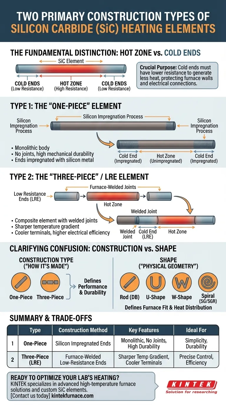
In silicon carbide (SiC) heating elements, the two primary types are defined by their construction method. These are the "one-piece" type, which has its colder ends impregnated with silicon metal, and the "three-piece" or Low Resistance End (LRE) type, which has separate, low-resistance ends furnace-welded to the central hot zone. This fundamental difference in how the non-heating ends are created dictates the element's performance characteristics.
The critical distinction between SiC element types is not their physical shape (rod, U, spiral), but how the cooler "cold ends" are joined to the main "hot zone." This engineering choice directly impacts electrical efficiency, temperature control, and mechanical durability.
The Fundamental Distinction: Hot Zone vs. Cold Ends
To understand the two construction types, you must first understand the basic anatomy of a resistance heating element. Its purpose is to generate heat, but only in a specific, controlled area.
What is a SiC Heating Element?
A silicon carbide heating element is a ceramic component that heats up when electrical current passes through it due to its inherent resistance. Made from high-purity SiC, these elements are valued for their ability to operate at extreme temperatures—up to 1600°C (2912°F)—and withstand harsh chemical environments and thermal shock.
The Critical Role of Cold Ends
The element must pass through the furnace's insulated wall to connect to the power supply. It is crucial that this section, known as the cold end or terminal, remains significantly cooler than the main heating section, or hot zone.
If the cold ends get too hot, they can damage the furnace wall, wiring, and electrical connectors. Therefore, they are engineered to have much lower electrical resistance than the hot zone, causing them to generate very little heat.
Deconstructing the Two Construction Types
The two primary types of SiC elements are differentiated by the method used to create these low-resistance cold ends.
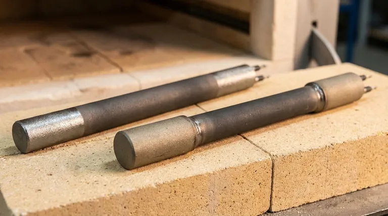
Type 1: The "One-Piece" Element
In this design, the element starts as a single, uniform rod or tube of silicon carbide. The ends of this rod are then impregnated with silicon metal.
This impregnation process fills the pores of the SiC ceramic, dramatically increasing its electrical conductivity in those areas. This lowers the resistance of the ends, turning them into effective cold ends while leaving the central, unimpregnated section as the high-resistance hot zone.
Type 2: The "Three-Piece" / LRE Element
This design uses a different approach. A separate, highly conductive type of silicon carbide material is manufactured specifically for the cold ends.
These low-resistance ends are then furnace-welded to the ends of the main high-resistance hot zone. This creates a composite element with three distinct sections, giving it the "three-piece" name. The term LRE simply stands for Low Resistance End, describing the function of the welded sections.
Understanding the Trade-offs
Neither construction method is universally superior; each offers a different balance of properties.
Durability and Failure Points
The "one-piece" element is a monolithic body, meaning it has no joints that could potentially serve as a point of mechanical failure.
The "three-piece" LRE design includes two welds. While these welds are created at extremely high temperatures and are exceptionally strong, they still represent a transition between different materials that can be a stress point under severe thermal cycling.
Electrical Efficiency and Temperature Gradient
The LRE design often allows for a more precisely engineered cold end with lower and more consistent resistance. This typically results in a sharper temperature drop-off between the hot zone and the furnace wall.
A sharper gradient means the element terminals run cooler, improving electrical connection integrity and potentially increasing overall energy efficiency.
Clarifying a Common Confusion: Construction vs. Shape
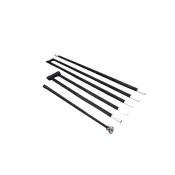
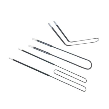
The references list various "types" like DB (Dumbbell/Rod), U, W, and Spiral (SG/SGR). It is vital to understand that these are not construction types but physical shapes or form factors.
Construction Type Defines the "How"
"One-piece" and "three-piece" refer to how the element is manufactured to create its hot and cold zones. This is the core engineering principle of the element.
Shape Defines the "What"
Shapes like Rod, U, W, and Spiral refer to the physical geometry of the element. This is chosen to fit the furnace design, distribute heat effectively, and meet the specific power requirements of the application. An element of almost any shape can be made using either the one-piece or three-piece construction method.
Making the Right Choice for Your Application
Selecting the correct element requires matching its construction and shape to your specific operational goals.
- If your primary focus is maximum mechanical simplicity: The "one-piece" design avoids welded joints, offering a single, continuous material body.
- If your primary focus is optimal electrical efficiency and cooler terminals: The "three-piece" LRE design typically provides a lower-resistance cold end for a more distinct temperature drop-off.
- If your primary focus is fitting a specific furnace: First select the shape (Rod, U, W, etc.) that best fits your chamber, and then specify the construction type based on your performance priorities.
Understanding the distinction between construction method and physical shape empowers you to specify the precise SiC element that meets your thermal and mechanical requirements.
Summary Table:
| Type | Construction Method | Key Features | Ideal For |
|---|---|---|---|
| One-Piece | Cold ends impregnated with silicon metal | Monolithic body, no joints, high mechanical durability | Applications prioritizing simplicity and durability |
| Three-Piece (LRE) | Low-resistance ends furnace-welded to hot zone | Sharper temperature gradient, cooler terminals, higher electrical efficiency | Applications needing precise temperature control and efficiency |
Ready to optimize your lab's heating efficiency? KINTEK specializes in advanced high-temperature furnace solutions, including Muffle, Tube, Rotary Furnaces, Vacuum & Atmosphere Furnaces, and CVD/PECVD Systems. With exceptional R&D and in-house manufacturing, we offer deep customization to meet your unique experimental needs. Contact us today to discuss how our SiC heating elements can enhance your performance!
Visual Guide
Related Products
- Silicon Carbide SiC Thermal Heating Elements for Electric Furnace
- Molybdenum Disilicide MoSi2 Thermal Heating Elements for Electric Furnace
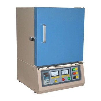
- 1400℃ Muffle Oven Furnace for Laboratory
People Also Ask
- How do silicon carbide heating elements enhance the heat treatment of alloys? Achieve Superior Temperature Control
- What are the temperature capabilities and mounting options for silicon carbide heating elements? Unlock High-Temp Flexibility and Durability
- What is the recommended surface load for silicon carbide heating elements at different furnace temperatures? Maximize Lifespan & Performance
- What are the advantages of using silicon carbide heating elements in industrial furnaces? Boost Efficiency and Durability
- What are some common types of silicon carbide heating elements? Explore Shapes, Coatings, and High-Temp Performance