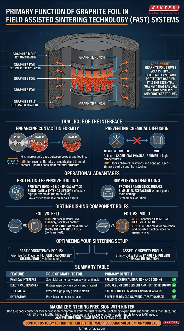
Graphite foil serves as a critical interface layer positioned directly between the raw powder and the mold or punch components within a Field Assisted Sintering Technology (FAST) system. Its primary purpose is to act as a protective physical barrier that prevents the sintering material from bonding to the tooling while simultaneously optimizing the uniformity of electrical and thermal transfer.
Core Insight: While the mold generates the heat and graphite felt insulates it, graphite foil is the essential "gasket" that ensures the process works. It bridges the gap between protecting expensive tooling and achieving high-quality, uniform sintering by mediating the contact points.
The Dual Role of the Interface
Enhancing Contact Uniformity
The microscopic surfaces of molds and punches are rarely perfectly smooth. Graphite foil is flexible and compressible, allowing it to conform to these irregularities.
By filling these gaps, the foil improves the uniformity of electrical and thermal contact across the interfaces. This ensures that the current and heat are distributed evenly into the powder, which is vital for achieving a consistent material structure.
Preventing Chemical Diffusion
At the high temperatures required for sintering, many powders become reactive and prone to diffusion bonding. Without a barrier, the sintered part could fuse to the mold or punches.
The graphite foil acts as a sacrificial physical barrier. It blocks chemical reactions between the powder and the mold components, ensuring the final part remains distinct from the tooling.
Operational Advantages
Protecting Expensive Tooling
High-purity graphite molds are costly precision components designed to withstand pressures up to 35 MPa. Direct contact with reactive powders can degrade or damage these molds rapidly.
By preventing bonding and chemical attack, the foil significantly extends the lifespan of the tooling. It is a low-cost consumable used to preserve high-cost assets.
Simplifying Demolding
Removing a sintered part from a mold can be difficult if adhesion occurs. Since the foil prevents the part from sticking to the mold walls or punches, it simplifies the demolding process.
This allows for easier extraction of the final component without damaging the part or the mold, streamlining the workflow.
Distinguishing Component Roles
Foil vs. Felt
It is crucial not to confuse graphite foil with graphite felt. While foil is an interface material placed inside the assembly, graphite felt is wrapped around the exterior of the mold.
Felt acts strictly as thermal insulation, reducing radiant heat loss to the vacuum chamber. Foil facilitates contact and separates materials; felt contains heat.
Foil vs. Mold
The graphite mold functions as both the container for the shape and the resistive heating element. The foil does not generate the primary heat nor constrain the shape; it simply lines the mold to ensure the mold can perform these functions repeatedly without degradation.
Optimizing Your Sintering Setup
To ensure successful FAST processing, select your materials based on the specific operational challenge you are facing:
- If your primary focus is Part Consistency: prioritize the placement of graphite foil to ensure uniform current distribution and avoid hot spots caused by poor contact.
- If your primary focus is Asset Longevity: strictly utilize graphite foil as a barrier to prevent chemical interaction and extend the usable life of your high-pressure molds.
Graphite foil is the indispensable intermediary that balances the aggressive physics of sintering with the delicate requirements of tool preservation.
Summary Table:
| Feature | Role of Graphite Foil | Primary Benefit |
|---|---|---|
| Physical Interface | Sacrificial barrier between powder and mold | Prevents chemical diffusion and bonding |
| Electrical Transfer | Bridges gaps between punch and material | Ensures uniform current and heat distribution |
| Tooling Care | Protects high-purity graphite molds | Extends the lifespan of expensive assets |
| Extraction | Provides a non-stick surface | Simplifies demolding without part damage |
Maximize Sintering Precision with KINTEK
Don't let poor contact or tool degradation compromise your material research. Backed by expert R&D and world-class manufacturing, KINTEK offers a comprehensive range of Muffle, Tube, Rotary, Vacuum, and CVD systems, along with specialized lab high-temp furnaces—all fully customizable to your specific Field Assisted Sintering Technology needs.
Our solutions are designed to help you achieve superior consistency and extend the life of your precision tooling. Contact us today to find the perfect thermal processing solution for your lab!
Visual Guide
References
- Alexander M. Laptev, Olivier Guillon. Tooling in Spark Plasma Sintering Technology: Design, Optimization, and Application. DOI: 10.1002/adem.202301391
This article is also based on technical information from Kintek Furnace Knowledge Base .
Related Products
People Also Ask
- What are the main types of sintering furnaces? Find the Perfect Match for Your Materials
- Why is it necessary to maintain a high vacuum environment during the SPS of SiC? Key to High-Density Ceramics
- What is unique about the heating mechanism of a Spark Plasma Sintering (SPS) furnace when preparing nanostructured h-BN ceramics? Achieve Ultra-Fast Densification and Suppress Grain Growth
- What is the significance of high-precision temperature monitoring systems in SPS? Control Ti-6Al-4V/HA Microstructure
- How does the heating mechanism of Spark Plasma Sintering (SPS) function? Enhance TiC/SiC Composite Fabrication