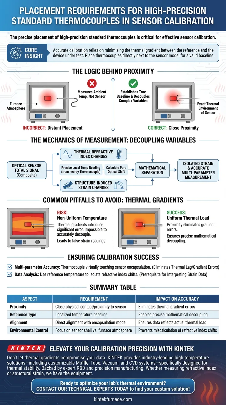
The precise placement of high-precision standard thermocouples is critical for effective sensor calibration. Specifically, these thermocouples must be positioned inside the heating furnace in extremely close proximity to the sensor encapsulation model. This physical nearness ensures the reference data reflects the exact thermal environment experienced by the sensor, rather than the general ambient temperature of the furnace.
Core Insight: Accurate calibration relies on minimizing the thermal gradient between the reference and the device under test. By placing standard thermocouples directly next to the sensor model, you create a valid baseline that allows for the mathematical separation of temperature effects from structural strain.
The Logic Behind Proximity
Establishing a True Baseline
The primary objective of placement is to establish a rigorous temperature reference baseline.
If the thermocouple is positioned at a distance from the sensor, it measures the furnace atmosphere rather than the sensor itself. Close proximity ensures that the recorded temperature aligns perfectly with the thermal energy acting upon the sensor encapsulation.
Decoupling Complex Variables
Optical sensors often output data that is a composite of multiple physical changes.
To achieve high-precision results, you must be able to separate—or "decouple"—these mixed signals. A precise local temperature reading is the key variable that allows you to mathematically untangle these factors.
The Mechanics of Measurement
Understanding Refractive Index Changes
Temperature fluctuations cause specific, predictable changes in the refractive index of the sensor material.
When you have an exact temperature reading from a nearby thermocouple, you can calculate exactly how much of the recorded wavelength shift is caused purely by these thermal optical properties.
Isolating Structural Strain
Once the thermal refractive index changes are identified, they can be subtracted from the total measurement.
The remaining data represents the structure-induced strain changes within the cavity length. Without the high-precision reference provided by close placement, separating strain from temperature becomes a matter of guesswork rather than calculation.
Common Pitfalls to Avoid
The Risk of Thermal Gradients
A common error is assuming the heating furnace has a perfectly uniform temperature distribution.
If the thermocouple is even a few centimeters away from the sensor encapsulation, thermal gradients can introduce significant error. This discrepancy makes it impossible to accurately decouple temperature effects, leading to false strain readings and degraded multi-parameter measurement accuracy.
Ensuring Calibration Success
To maximize the accuracy of your sensor calibration, adhere to these guidelines:
- If your primary focus is multi-parameter accuracy: Ensure the thermocouple is virtually touching the sensor encapsulation model to eliminate thermal lag and gradient errors.
- If your primary focus is data analysis: Use the reference temperature to mathematically isolate refractive index shifts before attempting to interpret strain data.
Precision in physical placement is the prerequisite for precision in digital measurement.
Summary Table:
| Placement Aspect | Requirement | Impact on Calibration Accuracy |
|---|---|---|
| Proximity | Close physical contact/proximity to sensor | Eliminates thermal gradient errors |
| Reference Type | Localized temperature baseline | Enables precise mathematical decoupling of variables |
| Alignment | Direct alignment with encapsulation model | Ensures data reflects sensor's actual thermal load |
| Environmental Control | Focus on sensor shell vs. furnace atmosphere | Prevents miscalculation of refractive index shifts |
Elevate Your Calibration Precision with KINTEK
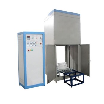
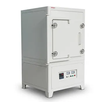
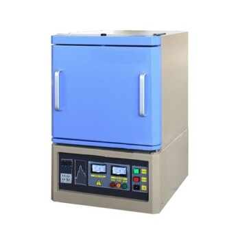
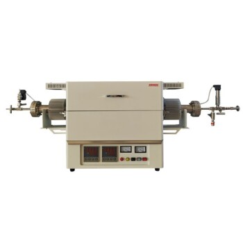
Don't let thermal gradients compromise your high-precision sensor data. KINTEK provides industry-leading high-temperature solutions—including customizable Muffle, Tube, Vacuum, and CVD systems—specifically designed to maintain the thermal stability required for rigorous calibration.
Backed by expert R&D and precision manufacturing, our lab furnaces empower you to isolate complex variables with confidence. Whether you are measuring refractive index shifts or structural strain, we have the specialized equipment to meet your unique needs.
Ready to optimize your lab's thermal environment? Contact our technical experts today to find your custom solution!
Visual Guide
References
- Zhichun Fan, Kevin P. Chen. A Hermetic Package Technique for Multi-Functional Fiber Sensors through Pressure Boundary of Energy Systems Based on Glass Sealants. DOI: 10.3390/photonics11090792
This article is also based on technical information from Kintek Furnace Knowledge Base .
Related Products
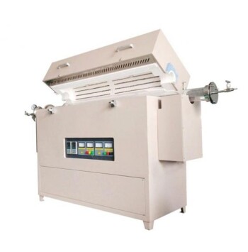
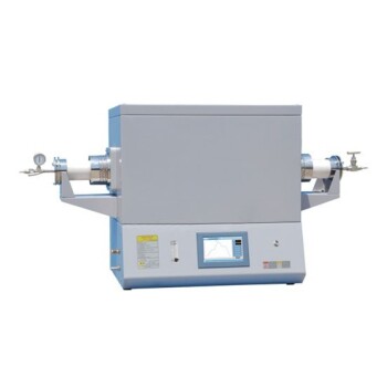
- Multi Zone Laboratory Quartz Tube Furnace Tubular Furnace
- Multi Heating Zones CVD Tube Furnace Machine for Chemical Vapor Deposition Equipment
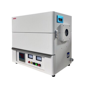
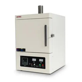
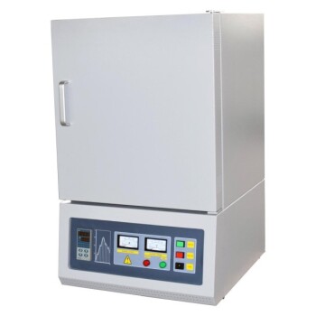
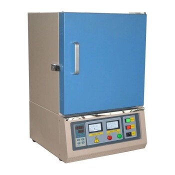
- High Temperature Muffle Oven Furnace for Laboratory Debinding and Pre Sintering
- Vertical Laboratory Quartz Tube Furnace Tubular Furnace
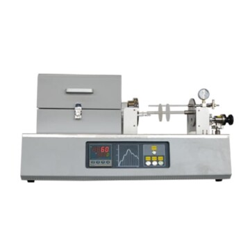
- 1200℃ Split Tube Furnace Laboratory Quartz Tube Furnace with Quartz Tube
People Also Ask
- What are the benefits of integrating multiple heating zones in a tube furnace? Unlock Precise Thermal Control
- How are multi zone tube furnaces used in ceramics, metallurgy and glass research? Unlock Precise Thermal Control for Advanced Materials
- What environmental protection applications utilize multi zone tube furnaces? Unlock Precision in Waste Treatment and Green Tech
- How does the temperature control system work in a multi gradient experimental tube furnace? Master Precise Heat Profiles for Your Lab
- What are the advantages of individually temperature-controlled zones in multi-zone furnaces? Unlock Precision Thermal Gradients