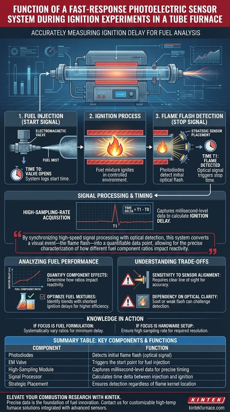
The primary function of a fast-response photoelectric sensor system is to accurately measure the ignition delay of fuels during combustion experiments. By utilizing strategically placed photodiodes to detect the initial flash of a flame, the system captures the precise time interval between the opening of the fuel injection valve and the onset of combustion.
By synchronizing high-speed signal processing with optical detection, this system converts a visual event—the flame flash—into a quantifiable data point, allowing for the precise characterization of how different fuel component ratios impact reactivity.
The Mechanics of Measurement
Strategic Sensor Placement
To ensure no data is lost, photodiodes are positioned at multiple locations within the combustion chamber.
This multi-point configuration ensures the system detects the ignition signal regardless of exactly where the flame kernel first develops in the tube.
Detecting the Flash Signal
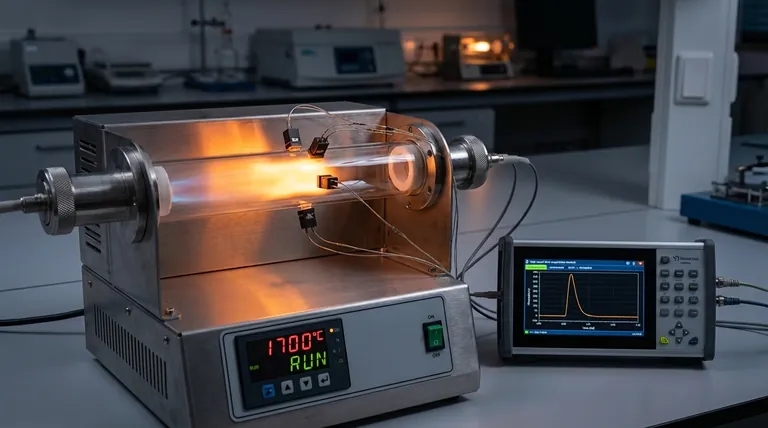
The core operational principle relies on optical monitoring. The sensors are tuned to detect the specific flash signals generated the instant fuel injection transitions into combustion.
This optical detection serves as the critical "stop" signal for the system's timing mechanism.
Signal Processing and Timing
High-Sampling-Rate Acquisition
Because ignition happens in milliseconds, standard recording speeds are insufficient.
The system employs high-sampling-rate signal processing and data acquisition modules. This high resolution is necessary to capture the minute time differences between mechanical action and chemical reaction.
Calculating the Time Delta
The system logically connects two distinct events: the opening of the electromagnetic valve (the fuel injection start) and the reception of the optical flame signal.
The time elapsed between these two events is calculated to determine the ignition delay.
Analyzing Fuel Performance
Quantifying Component Effects
The ultimate goal of this setup is not just to see if the fuel burns, but how fast.
By quantifying the ignition delay, researchers can determine how changing the ratios of different components in a composite fuel affects its performance.
Optimizing Fuel Mixtures
This data allows for empirical comparison.
It enables scientists to identify which specific fuel blends offer the shortest ignition delays, indicating higher reactivity and potentially better combustion efficiency.
Understanding the Trade-offs
Sensitivity to Sensor Alignment
The accuracy of the system depends heavily on the "line of sight" of the photodiodes.
If sensors are obstructed or poorly positioned, there may be a slight lag between the actual ignition and the detection, introducing error into the delay calculation.
Dependency on Optical Clarity
Because the system is photoelectric, it relies entirely on light detection.
Factors that obscure light, such as heavy soot accumulation on the sensor windows or extremely weak initial flashes, can challenge the system's ability to trigger the "stop" signal accurately.
Making the Right Choice for Your Goal
To maximize the value of a fast-response photoelectric system in your experiments, consider your specific objectives:
- If your primary focus is fuel formulation: Use the ignition delay data to systematically vary component ratios until you achieve the minimum possible delay time.
- If your primary focus is hardware setup: Ensure your data acquisition module has a sampling rate high enough to resolve the specific time scales (milliseconds or microseconds) relevant to your fuel type.
This system ultimately transforms the complex physics of ignition into a single, precise metric that drives better fuel design.
Summary Table:
| Component | Function |
|---|---|
| Photodiodes | Detects initial flame flash (optical signal) |
| EM Valve | Triggers the start point for fuel injection |
| High-Sampling Module | Captures millisecond-level data for precise timing |
| Signal Processor | Calculates time delta between injection and ignition |
| Strategic Placement | Ensures detection regardless of flame kernel location |
Elevate Your Combustion Research with KINTEK
Precise data is the foundation of fuel innovation. At KINTEK, we understand that ignition experiments require absolute accuracy and high-speed reliability. Backed by expert R&D and world-class manufacturing, we offer a comprehensive range of Tube, Muffle, Rotary, Vacuum, and CVD systems, all of which are fully customizable to integrate advanced sensor technologies like fast-response photoelectric systems.
Whether you are optimizing fuel mixtures or researching reaction kinetics, our specialized laboratory high-temp furnaces provide the stable, controlled environment your work demands.
Ready to refine your thermal processing? Contact us today to discuss your unique project needs with our technical team.
Visual Guide
Related Products
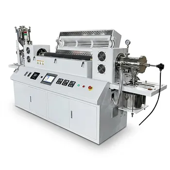
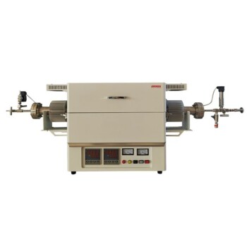
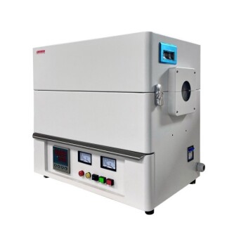
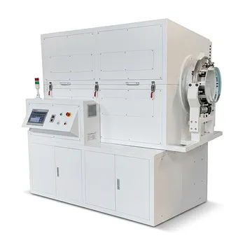
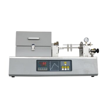
- Vacuum Sealed Continuous Working Rotary Tube Furnace Rotating Tube Furnace
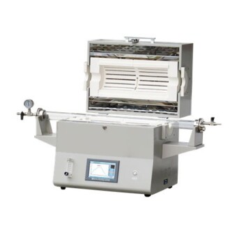
- 1400℃ High Temperature Laboratory Tube Furnace with Alumina Tube
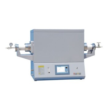
- 1700℃ High Temperature Laboratory Tube Furnace with Alumina Tube
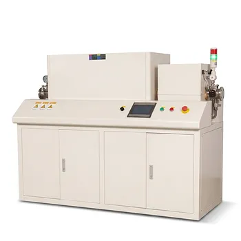
- Magnesium Extraction and Purification Condensing Tube Furnace
- High Pressure Laboratory Vacuum Tube Furnace Quartz Tubular Furnace
People Also Ask
- What is the purpose of rotary tube furnaces? Achieve Uniform Heat Treatment for Powders and Granules
- What optional features enhance the processing capabilities of rotary tube furnaces? Boost Efficiency with Advanced Customizations
- What are the key advantages of using a rotary tube furnace? Achieve Dynamic, Uniform Heating for Powders
- What are the advantages of rotary tube furnaces in fuel compatibility? Boost Efficiency and Cut Costs
- When are rotary tube furnaces not suitable for a process? Avoid Costly Mistakes in Thermal Processing