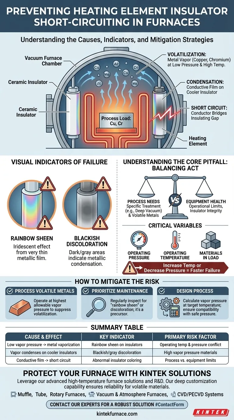
Short-circuiting of heating element insulators is primarily caused by operating a furnace at a vapor pressure that is too low for the materials being processed. This condition allows conductive metals within the process load, such as copper or chromium, to vaporize and then condense as a thin, conductive film on the cooler insulator surfaces, creating an unintended electrical path.
The core issue is a physical transformation: incorrect furnace pressure can turn non-conductive insulators into live conductors by coating them with vaporized metal from the parts you are processing. This fundamentally compromises the furnace's electrical integrity.
The Core Mechanism: From Solid Metal to Conductive Film
To prevent this failure, it is essential to understand the step-by-step process that leads to the short circuit. It is not an instantaneous event but a gradual degradation driven by the physics of the furnace environment.
The Role of Vapor Pressure
Every material has a vapor pressure, which is the pressure at which it will transition from a solid or liquid into a gas at a given temperature.
Operating a furnace at a very low pressure (a high vacuum) significantly lowers the temperature needed for materials to vaporize.
Volatilization of Process Metals
Metals like copper and chromium are particularly susceptible to this. At high temperatures and low pressures, atoms of these metals will escape the surface of the process load and become a metallic vapor within the furnace chamber.
This process is known as volatilization or evaporation.
The Condensation Problem
The heating element insulators are, by design, often slightly cooler than the heating elements and the process load itself.
This temperature difference creates a condensation point. The metal vapor circulating in the furnace will preferentially condense back into a solid on these cooler insulator surfaces.
Creating the Short Circuit
Over time, this condensation builds up into a thin, metallic film. Because this film is electrically conductive, it bridges the insulating gap.
This creates a new, low-resistance path for electricity, causing a short circuit that can damage or destroy the heating elements and power supply.
Identifying the Problem Before Failure
Catastrophic failure can often be preceded by clear visual warnings on the insulators. Proactive inspection is key to preventing costly downtime.
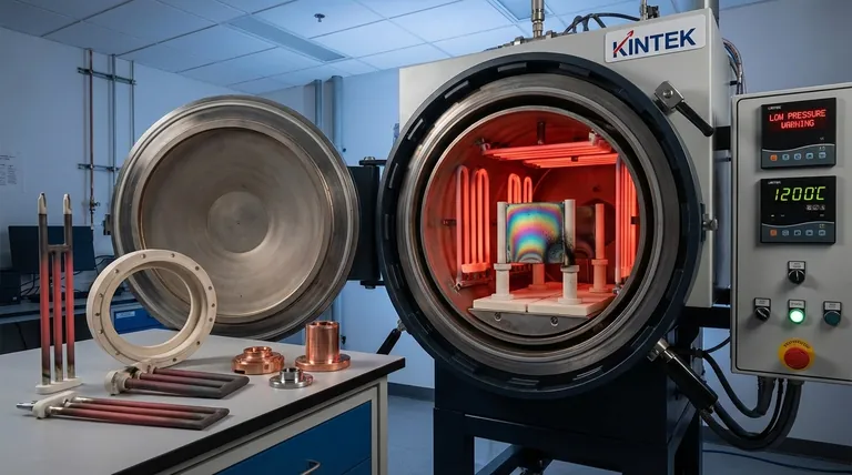
The "Rainbow Sheen"
One of the most common indicators is a "rainbow sheen" on the ceramic insulator. This iridescent effect is characteristic of a very thin metallic film being deposited on the surface.
Blackish Discoloration
In other cases, the condensation may appear as a simple blackish or gray area. Any discoloration that deviates from the normal appearance of the ceramic should be considered a potential sign of metallic condensation.
Understanding the Key Pitfall
The central challenge lies in balancing the requirements of the metallurgical process with the operational limits of the furnace hardware.
Process Needs vs. Equipment Health
The low vapor pressure causing the issue might be a deliberate and necessary parameter for the specific treatment process.
However, running a process that requires a deep vacuum while heating materials known to have a high vapor pressure creates a direct conflict that puts equipment at high risk.
The Critical Variables
The risk of insulator short-circuiting is a function of three main variables: the operating pressure, the operating temperature, and the materials in the load.
An increase in temperature or a decrease in pressure will dramatically accelerate the vaporization of volatile metals, leading to faster insulator failure.
How to Mitigate the Risk
Your operational strategy must account for the physical properties of the materials you are processing to ensure furnace reliability.
- If your primary focus is processing volatile metals (like copper): You must operate at the highest allowable vapor pressure for your process to suppress the volatilization of the metal.
- If your primary focus is maintenance and reliability: Regularly inspect insulators for any discoloration, especially the characteristic "rainbow sheen," as this is a direct precursor to failure.
- If your primary focus is process design: You must calculate the vapor pressure of your load materials at the target temperature and ensure it is compatible with the furnace's minimum safe operating pressure.
Understanding this relationship between pressure, temperature, and material science is the key to preventing this destructive failure mode.
Summary Table:
| Cause & Effect | Key Indicator | Primary Risk Factor |
|---|---|---|
| Low vapor pressure causes metal (Cu, Cr) vaporization | Rainbow sheen on insulators | Operating temperature & pressure conflict |
| Metal vapor condenses on cooler insulators | Blackish/gray discoloration | High vapor pressure materials in load |
| Conductive film creates electrical short circuit | Any abnormal insulator coloring | Process parameters vs. equipment limits |
Protect your furnace from destructive short-circuiting. The delicate balance between process parameters and equipment limits is critical. At KINTEK, we leverage our exceptional R&D and in-house manufacturing to provide advanced high-temperature furnace solutions precisely engineered to handle volatile materials. Our product line—including Muffle, Tube, Rotary Furnaces, Vacuum & Atmosphere Furnaces, and CVD/PECVD Systems—is backed by strong deep customization capability to meet your unique experimental requirements and prevent failures. Contact our experts today to design a robust furnace solution for your lab (#ContactForm).
Visual Guide
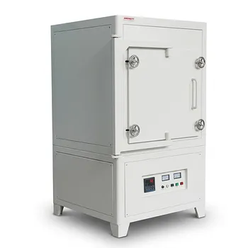
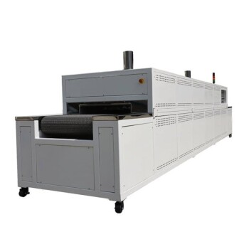
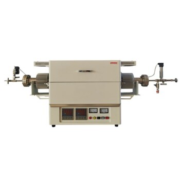
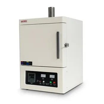
Related Products
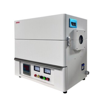
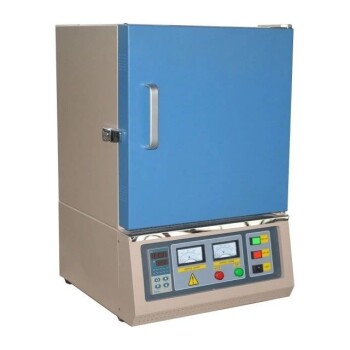
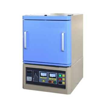
- High Temperature Muffle Oven Furnace for Laboratory Debinding and Pre Sintering
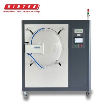
- 1200℃ Controlled Inert Nitrogen Atmosphere Furnace
- Mesh Belt Controlled Atmosphere Furnace Inert Nitrogen Atmosphere Furnace
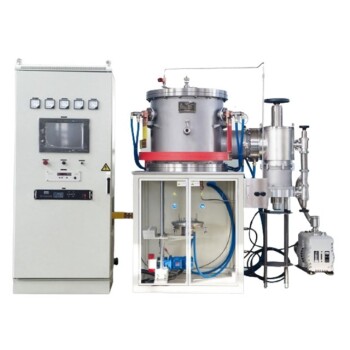
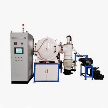
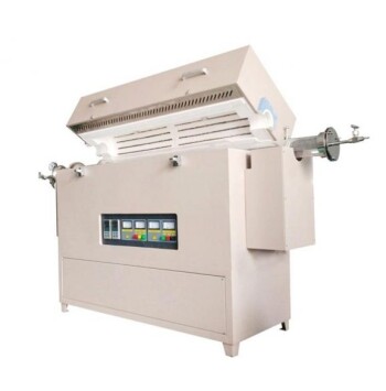
- High Pressure Laboratory Vacuum Tube Furnace Quartz Tubular Furnace
- 1200℃ Muffle Oven Furnace for Laboratory
People Also Ask
- Why is a two-stage sintering process used for porous LATP? Master Structural Integrity and Porosity
- What is the function of a laboratory high-temperature muffle furnace in niobate phosphor synthesis?
- What role does a high-temperature muffle furnace play in STFO synthesis? Achieve Pure Perovskite Results
- Why use a high-temp muffle furnace for zirconia coating thermal cycling? Simulate extreme stress & ensure durability.
- What is the function of a high-temperature muffle furnace in Belite research? Optimize Polymorphic Phase Transitions