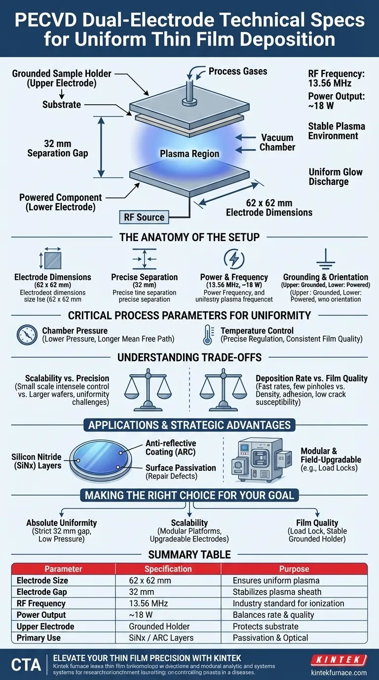
The technical standard for a capacitively coupled dual-electrode configuration in Plasma Enhanced Chemical Vapor Deposition (PECVD) typically utilizes two square electrodes measuring approximately 62 x 62 mm, separated by a gap of 32 mm. This geometry is powered by a 13.56 MHz Radio Frequency (RF) source operating at approximately 18 W to maintain a stable plasma environment.
Core Takeaway While precise dimensions are critical, the effectiveness of this configuration lies in its ability to sustain a uniform glow discharge. This specific electrode spacing and power ratio are engineered to maximize the consistency of film thickness and material properties across the substrate.
The Anatomy of the Dual-Electrode Setup
Electrode Dimensions and Geometry
The core of this configuration involves two parallel plates. The standard specification calls for electrodes measuring roughly 62 x 62 mm.
These dimensions are specifically chosen to support uniform plasma distribution over the target area.
Precise Separation Distance
The electrodes are positioned with a fixed separation of 32 mm.
This specific gap is critical; it allows the plasma sheath to form correctly without collapsing or becoming unstable, ensuring the glow discharge fills the volume evenly.
Power and Frequency Specifications
The system is driven by an industry-standard 13.56 MHz RF power source.
Operating at a power level of approximately 18 W, this setup provides sufficient energy to ionize the process gases without inducing excessive ion bombardment damage to the film.
Grounding and Sample Orientation
In this configuration, the upper electrode typically serves as the grounded sample holder.
The lower electrode is the powered component. This arrangement isolates the substrate from potential fluctuations in the drive voltage, contributing to a more controlled deposition environment.
Critical Process Parameters for Uniformity
The Role of Pressure
While the electrode geometry sets the stage, chamber pressure dictates the physics of the deposition.
Lower pressures generally result in a longer mean free path for particles. This improves the uniformity of the deposition across the substrate surface.
Temperature Control
Precise temperature regulation is non-negotiable for consistent film quality.
Although PECVD allows for lower basic process temperatures compared to other CVD methods, maintaining a stable thermal profile ensures that chemical reactions occur at a consistent rate across the entire wafer.
Understanding the Trade-offs
Scalability vs. Precision
The specified 62 x 62 mm configuration is highly effective for research and small-scale applications, offering intense control.
However, industrial requirements often demand processing 2-inch, 4-inch, or up to 6-inch wafers. Scaling this configuration requires larger electrodes, which introduces new challenges in maintaining plasma uniformity across the wider surface area.
Deposition Rate vs. Film Quality
PECVD is prized for its fast deposition rates and ability to produce films with fewer pinholes.
However, there is often a balance to strike. Pushing for maximum speed can sometimes compromise the density or adhesion of the film. Conversely, optimizing for the highest quality (such as low crack susceptibility) may require slower, more conservative process parameters.
Applications and Strategic Advantages
Dual-Purpose Functionality
A prime example of this configuration's utility is the deposition of Silicon Nitride (SiNx) layers.
This layer acts as an anti-reflective coating (ARC) to reduce optical losses. Simultaneously, the hydrogen introduced during the process passivates the silicon surface, repairing defects and enhancing carrier lifetime.
Operational Flexibility
Modern PECVD systems built on this platform are often modular and field-upgradable.
Options such as load locks can be added to isolate the process chamber from the ambient atmosphere. This prevents contamination and further stabilizes the vacuum environment, though it adds to system complexity and cost.
Making the Right Choice for Your Goal
The optimal setup depends on whether you are prioritizing strictly uniform research results or higher throughput for production.
- If your primary focus is Absolute Uniformity: Adhere strictly to the 32 mm separation and low-pressure parameters to maximize the mean free path and plasma stability.
- If your primary focus is Scalability: Look for modular platforms that allow you to upgrade electrode sizes (e.g., for 4 or 6-inch wafers) without replacing the entire RF power architecture.
- If your primary focus is Film Quality (Defect Reduction): Prioritize systems with a load lock to eliminate atmospheric contamination and ensure the stability of the grounded sample holder.
Success in PECVD comes from balancing the rigid geometry of the electrodes with the fluid dynamics of pressure and temperature.
Summary Table:
| Parameter | Specification | Purpose |
|---|---|---|
| Electrode Size | 62 x 62 mm | Ensures uniform plasma distribution |
| Electrode Gap | 32 mm | Stabilizes plasma sheath & glow discharge |
| RF Frequency | 13.56 MHz | Industry standard for gas ionization |
| Power Output | ~18 W | Balances deposition rate with film quality |
| Upper Electrode | Grounded Holder | Protects substrate from voltage fluctuations |
| Primary Use | SiNx / ARC Layers | Surface passivation and optical optimization |
Elevate Your Thin Film Precision with KINTEK
Achieving perfect film uniformity requires more than just standard specs; it demands high-performance hardware engineered for stability. KINTEK provides industry-leading PECVD systems, Muffle, Tube, and Vacuum furnaces, all backed by our expert R&D and manufacturing teams. Whether you are processing small research samples or scaling to 6-inch wafers, our systems are fully customizable to meet your unique laboratory needs.
Ready to optimize your deposition process? Contact our technical experts today to discuss how our modular high-temperature solutions can enhance your research outcomes.
Visual Guide
References
- Z. Remeš, Oleg Babčenko. Thin Hydrogenated Amorphous Silicon Carbide Layers with Embedded Ge Nanocrystals. DOI: 10.3390/nano15030176
This article is also based on technical information from Kintek Furnace Knowledge Base .
Related Products
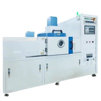
- RF PECVD System Radio Frequency Plasma Enhanced Chemical Vapor Deposition
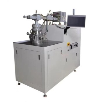
- Slide PECVD Tube Furnace with Liquid Gasifier PECVD Machine
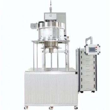
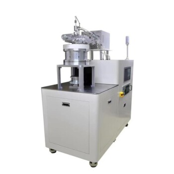
- Inclined Rotary Plasma Enhanced Chemical Deposition PECVD Tube Furnace Machine
- Inclined Rotary Plasma Enhanced Chemical Deposition PECVD Tube Furnace Machine
- Cylindrical Resonator MPCVD Machine System for Lab Diamond Growth
People Also Ask
- What is the role of RF power in PECVD and how does the RF-PECVD process work? Master Thin Film Deposition Control
- What are the limitations of PECVD? Overcome Process Control and Cost Challenges
- What are the key advantages of PECVD technology? Achieve Low-Temperature, High-Quality Thin Film Deposition
- What are the applications of plasma enhanced chemical vapor deposition? Key Uses in Electronics, Optics & Materials
- What are some promising applications of PECVD-prepared 2D materials? Unlock Advanced Sensing and Optoelectronics