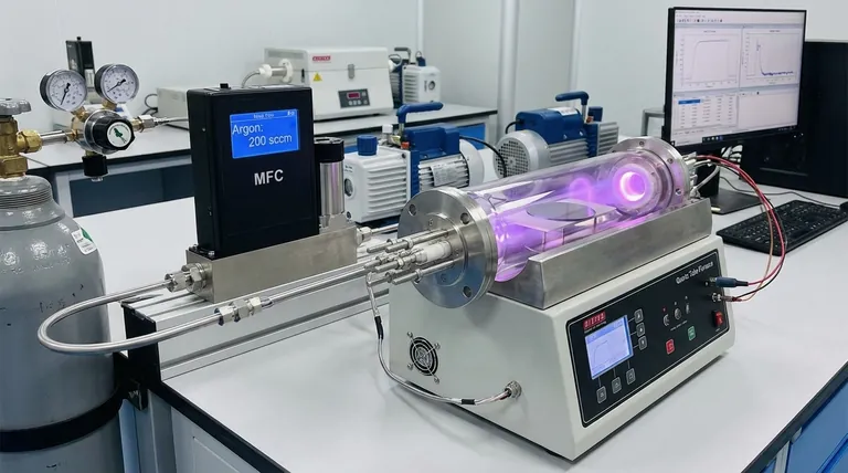
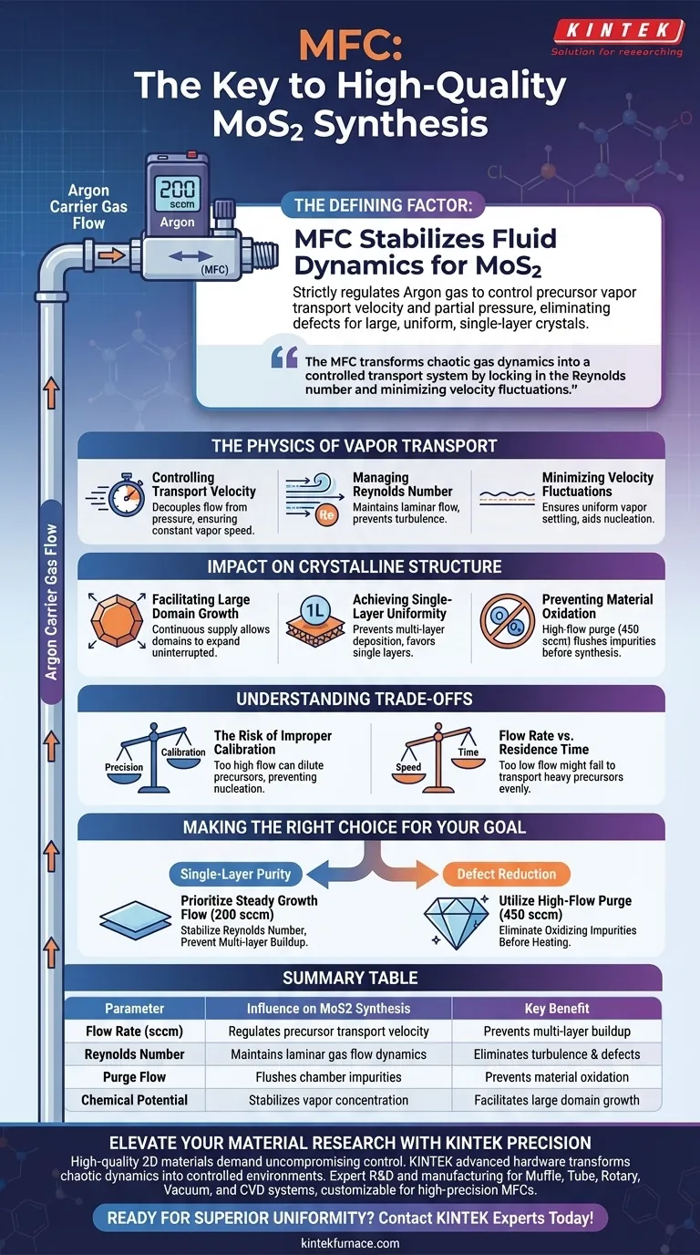
The use of a mass flow controller (MFC) is the defining factor in stabilizing the fluid dynamics required for high-quality MoS2 synthesis. By strictly regulating the Argon carrier gas—typically at a rate of 200 sccm—the MFC controls the transport velocity and partial pressure of precursor vapors. This precision eliminates the environmental variables that lead to defects, ensuring the growth of large, uniform, and single-layer crystalline domains.
The MFC transforms chaotic gas dynamics into a controlled transport system. By locking in the Reynolds number and minimizing velocity fluctuations, it creates the stable environment necessary for growing atomic-scale MoS2 structures with consistency.
The Physics of Vapor Transport
Controlling Transport Velocity
The primary role of the MFC is to decouple gas flow from external pressure variations. By maintaining a fixed flow rate (e.g., 200 sccm), it ensures that precursor vapors are transported to the substrate at a constant, calculated speed.
Managing the Reynolds Number
The quality of MoS2 growth is governed by fluid dynamics, specifically the Reynolds number within the reaction chamber. The MFC maintains this number within a specific range to ensure the gas flow remains laminar rather than turbulent.
Minimizing Velocity Fluctuations
Turbulence or erratic gas pulses at the substrate surface can disrupt the nucleation process. Accurate regulation by the MFC minimizes these velocity fluctuations, ensuring the vapor settles uniformly across the target area.
Impact on Crystalline Structure
Facilitating Large Domain Growth
To achieve large crystal domains, the supply of precursors must be continuous and steady. The MFC ensures that the chemical potential at the growth front remains constant, allowing domains to expand without interruption.
Achieving Single-Layer Uniformity
Variations in gas flow can lead to unpredictable spikes in precursor concentration. By stabilizing the flow, the MFC prevents the accidental deposition of multi-layers, favoring the formation of uniform single-layer MoS2.
Preventing Material Oxidation
Beyond growth kinetics, the MFC allows for precise high-flow purging sequences (often around 450 sccm) prior to synthesis. This effectively flushes air impurities from the chamber, preventing oxidation that would degrade the MoS2 quality.
Understanding the Trade-offs
The Risk of Improper Calibration
While an MFC provides precision, it requires the operator to select the correct setpoint for the specific reactor geometry. An MFC set too high can dilute the precursor concentration, preventing nucleation entirely.
Flow Rate vs. Residence Time
There is a delicate balance between transport speed and the time vapors spend over the substrate. If the MFC is set too low to increase residence time, it may fail to transport heavy precursors effectively, leading to uneven coverage.
Making the Right Choice for Your Goal
To maximize the quality of your MoS2 synthesis, adjust your MFC strategy based on your specific quality metrics:
- If your primary focus is Single-Layer Purity: Prioritize a steady growth flow (e.g., 200 sccm) to stabilize the Reynolds number and prevent multi-layer buildup.
- If your primary focus is Defect Reduction: Utilize the MFC to execute a high-flow purge cycle (e.g., 450 sccm) before heating to eliminate oxidizing impurities.
Precision in gas flow is not just an operational detail; it is the control variable that dictates the structural integrity of your nanomaterials.
Summary Table:
| Parameter | Influence on MoS2 Synthesis | Key Benefit |
|---|---|---|
| Flow Rate (sccm) | Regulates precursor transport velocity | Prevents multi-layer buildup |
| Reynolds Number | Maintains laminar gas flow dynamics | Eliminates turbulence & defects |
| Purge Flow | Flushes chamber impurities | Prevents material oxidation |
| Chemical Potential | Stabilizes vapor concentration | Facilitates large domain growth |
Elevate Your Material Research with KINTEK Precision
High-quality 2D materials like MoS2 demand uncompromising control over every variable. KINTEK provides the advanced hardware necessary to transform chaotic gas dynamics into a controlled growth environment.
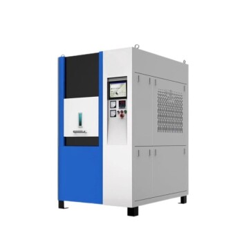
Backed by expert R&D and manufacturing, KINTEK offers Muffle, Tube, Rotary, Vacuum, and CVD systems, all fully customizable to integrate high-precision MFCs and specialized reactor geometries for your unique research needs.
Ready to achieve superior crystalline uniformity? Contact our technical experts today to design a high-temperature furnace system tailored to your lab’s requirements.
Visual Guide
References
- Feng Liao, Zewen Zuo. Optimizing the Morphology and Optical Properties of MoS2 Using Different Substrate Placement: Numerical Simulation and Experimental Verification. DOI: 10.3390/cryst15010059
This article is also based on technical information from Kintek Furnace Knowledge Base .
Related Products
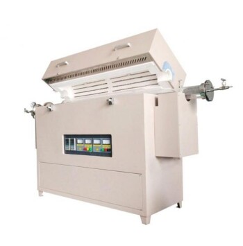
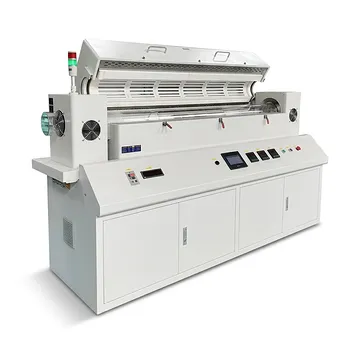
- Multi Heating Zones CVD Tube Furnace Machine for Chemical Vapor Deposition Equipment
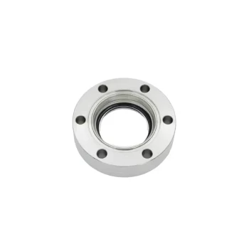
- CF KF Flange Vacuum Electrode Feedthrough Lead Sealing Assembly for Vacuum Systems
- Ultra-High Vacuum Flange Aviation Plug Glass Sintered Airtight Circular Connector for KF ISO CF
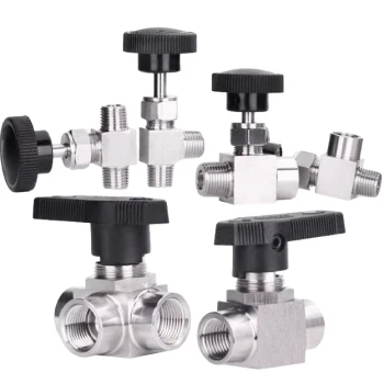
- High Performance Vacuum Bellows for Efficient Connection and Stable Vacuum in Systems
- Multi Zone Laboratory Quartz Tube Furnace Tubular Furnace
People Also Ask
- What temperature-related capabilities make multi zone tube furnaces valuable for research? Unlock Precision Thermal Control
- What are the benefits of integrating multiple heating zones in a tube furnace? Unlock Precise Thermal Control
- What role does a Tube Furnace play in the CVD growth of carbon nanotubes? Achieve High-Purity CNT Synthesis
- What are the advantages of multi-zone tube furnaces? Achieve Superior Thermal Control for Advanced Materials Processing
- What role do multi zone tube furnaces play in new energy research? Unlock Precise Thermal Control for Innovation