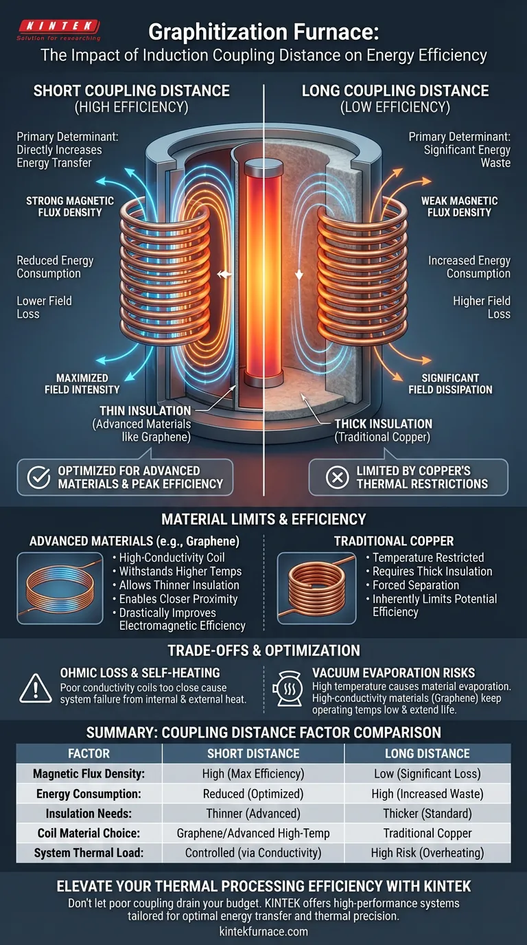
The physical coupling distance is the primary determinant of electromagnetic energy transfer efficiency. In a graphitization furnace, the gap between the induction coil and the heating element dictates how effectively the magnetic field is utilized. A shorter coupling distance minimizes energy waste and maximizes field intensity, leading to significantly reduced overall energy consumption.
By minimizing the physical distance between the coil and the heating element, you directly increase the efficiency of magnetic field energy transfer. However, this proximity is strictly limited by the thermal capabilities of the coil material and the required insulation thickness.
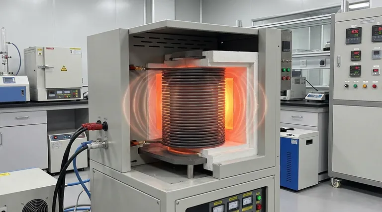
The Physics of Coupling Efficiency
The Inverse Relationship
The relationship between coupling distance and efficiency is straightforward: closer is better.
As the distance between the induction coil and the heating element decreases, the magnetic flux density acting on the target increases.
Minimizing Field Loss
When the gap is large, a significant portion of the electromagnetic field dissipates before it can induce current in the heating element.
Tightening this physical coupling ensures that the maximum amount of generated energy is converted directly into heat within the graphitization zone.
The Insulation Barrier
The Space Requirement
In practical applications, you cannot simply place a bare coil against a high-temperature heating element.
There must be a physical barrier—thermal insulation—to protect the coil from the intense heat of the furnace.
The Distance Penalty
This insulation layer creates an unavoidable physical gap, or "standoff distance."
The thicker the required insulation, the lower the electromagnetic efficiency of the system.
Material Limits and Efficiency
The Limitations of Copper
Traditional copper induction coils face significant temperature restrictions.
To prevent failure, copper coils require thick layers of insulation to separate them from the heat source.
This forced separation results in a larger coupling distance, inherently limiting the system's potential energy efficiency.
The Advantage of Advanced Materials
Advanced materials, such as graphene induction coils, fundamentally change this equation.
Because these materials can withstand different thermal conditions, they allow for much thinner insulation layers.
This enables the coil to be placed significantly closer to the heating element, drastically improving electromagnetic efficiency compared to copper.
Understanding the Trade-offs
Ohmic Loss and Self-Heating
Bringing a coil closer to the heat source is risky if the coil generates its own internal heat.
The coil's material must have high electrical conductivity to minimize ohmic loss (resistance-based heating).
If a coil with poor conductivity is placed too close to the furnace core, the combination of internal self-heating and external radiated heat will lead to system failure.
Vacuum Evaporation Risks
In high-temperature vacuum conditions, material stability becomes a critical factor.
If the coil runs too hot due to proximity or self-heating, the material may begin to evaporate.
Using high-conductivity materials (like graphene) keeps the coil operating temperature low, preventing evaporation and extending the service life of the induction system.
Optimizing Your Graphitization Setup
Balancing Distance and Durability
To achieve peak efficiency, you must balance the desire for close coupling with the thermal reality of your coil material.
If your primary focus is Maximum Energy Efficiency:
- Prioritize advanced coil materials like graphene that allow for minimal insulation thickness and the shortest possible physical coupling distance.
If your primary focus is Component Longevity:
- Ensure the coil material has high electrical conductivity to minimize self-heating, preventing material evaporation even when placed in close proximity to the heat source.
If your primary focus is Cost of Implementation (Traditional):
- Accept that standard copper coils will require larger coupling distances and thicker insulation, resulting in lower electromagnetic efficiency and higher operational energy costs.
The most efficient system is one that safely minimizes the gap between the energy source and the target without compromising thermal stability.
Summary Table:
| Factor | Short Coupling Distance | Long Coupling Distance |
|---|---|---|
| Magnetic Flux Density | High (Maximum Efficiency) | Low (Significant Field Loss) |
| Energy Consumption | Reduced (Optimized Transfer) | High (Increased Waste) |
| Insulation Needs | Thinner (Advanced Materials) | Thicker (Standard Materials) |
| Coil Material Choice | Graphene/Advanced High-Temp | Traditional Copper |
| System Thermal Load | Controlled via Conductivity | High Risk of Overheating |
Elevate Your Thermal Processing Efficiency with KINTEK
Don't let poor electromagnetic coupling drain your operational budget. Backed by expert R&D and manufacturing, KINTEK offers high-performance Muffle, Tube, Rotary, Vacuum, and CVD systems designed to optimize energy transfer and thermal precision. Whether you need custom-engineered induction setups or specialized lab high-temperature furnaces, our solutions are tailored to meet your unique materials science requirements.
Ready to optimize your graphitization setup? Contact us today to discover how KINTEK's advanced manufacturing can deliver the efficiency and durability your lab demands.
Visual Guide
References
- Rui Li, Hongda Du. Design and Numerical Study of Induction-Heating Graphitization Furnace Based on Graphene Coils. DOI: 10.3390/app14062528
This article is also based on technical information from Kintek Furnace Knowledge Base .
Related Products
- 2200 ℃ Graphite Vacuum Heat Treat Furnace
- Spark Plasma Sintering SPS Furnace
- Small Vacuum Heat Treat and Tungsten Wire Sintering Furnace
- 1400℃ High Temperature Laboratory Tube Furnace with Alumina Tube
- Controlled Inert Nitrogen Hydrogen Atmosphere Furnace
People Also Ask
- Why are vacuum heat treating furnaces essential for aerospace? Ensure Superior Material Integrity for High-Stakes Applications
- What is the primary application of vacuum heat treating furnaces in aerospace? Enhance Component Performance with Precision
- How does a vacuum heat treating furnace improve the condition of metal alloys? Achieve Superior Metal Performance
- What is the process of vacuum heat treating? Achieve Superior Metallurgical Properties
- How does vacuum heat treating work in terms of temperature and time control? Master Precise Material Transformations