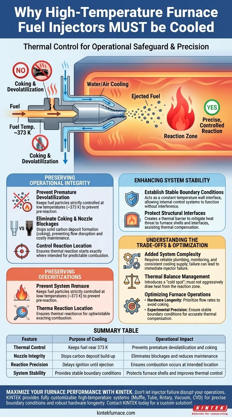
In high-temperature furnace environments, cooling is a critical operational safeguard. Fuel injectors must utilize water or air cooling to maintain fuel temperatures at approximately 373 K, strictly preventing the fuel from reacting before it leaves the nozzle. This thermal control is the only way to ensure the injector does not suffer from internal clogging or structural failure.
By keeping fuel particles at low temperatures until ejection, cooling systems prevent premature devolatilization and internal coking. This ensures that thermal reactions occur precisely where intended—inside the chamber, not inside the hardware.
Preserving Operational Integrity
Preventing Premature Devolatilization
The primary function of the cooling system is to keep fuel particles strictly controlled at low levels (around 373 K).
If the fuel heats up too early, it begins to devolatilize inside the injector body. This alters the chemical composition of the fuel before it ever reaches the reaction zone.
Eliminating Coking and Nozzle Blockages
When fuel overheats within the confined space of an injector, it leads to "coking"—the formation of solid carbon deposits.
Without active cooling, these deposits would rapidly accumulate. This accumulation inevitably leads to physical nozzle blockages, disrupting flow and requiring expensive maintenance.
Controlling Reaction Location
Precision is paramount in high-temperature systems.
The cooling mechanism ensures that the fuel particles begin their thermal reaction exactly at the intended location within the furnace. By preventing early ignition inside the nozzle, the system maintains a predictable and efficient combustion profile.
Enhancing System Stability
Establishing Stable Boundary Conditions
Beyond protecting the fuel, the cooling system acts as a constant temperature wall interface.
This establishes stable external boundary conditions for the furnace. Stability here allows the internal control systems to function without interference from fluctuating injector temperatures.
Protecting Structural Interfaces
High-temperature environments pose a threat to the structural integrity of furnace shells and specific interfaces.
The cooling system mitigates this risk by maintaining a thermal barrier. This assists the internal temperature control system in achieving accurate thermal compensation and protects the physical hardware.
Understanding the Trade-offs
Added System Complexity
Implementing water or air cooling adds a layer of mechanical complexity to the furnace design.
It requires reliable plumbing, monitoring, and a consistent supply of the cooling medium. A failure in the cooling supply line can lead to immediate injector failure.
Thermal Balance Management
While cooling is necessary for the injector, it introduces a "cold spot" into a hot environment.
Operators must ensure the cooling system does not aggressively draw heat away from the reaction zone itself. The goal is to cool the hardware and fuel, not the furnace chamber.
Optimizing Furnace Operations
To ensure long-term reliability and precision in your high-temperature applications, consider the following:
- If your primary focus is hardware longevity: Prioritize cooling flow rates that strictly maintain the injector interface below the coking threshold to prevent nozzle blockages.
- If your primary focus is experimental precision: Ensure the cooling system provides a stable boundary condition to assist the internal temperature control system in maintaining accurate thermal compensation.
The correct application of injector cooling transforms a volatile, clog-prone setup into a consistent, high-precision reaction system.
Summary Table:
| Feature | Purpose of Cooling | Operational Impact |
|---|---|---|
| Thermal Control | Keeps fuel near 373 K | Prevents premature devolatilization and coking |
| Nozzle Integrity | Stops carbon deposit build-up | Eliminates blockages and reduces maintenance |
| Reaction Precision | Delays ignition until ejection | Ensures combustion occurs at the intended location |
| System Stability | Provides stable boundary conditions | Protects furnace shells and improves thermal control |
Maximize Your Furnace Performance with KINTEK
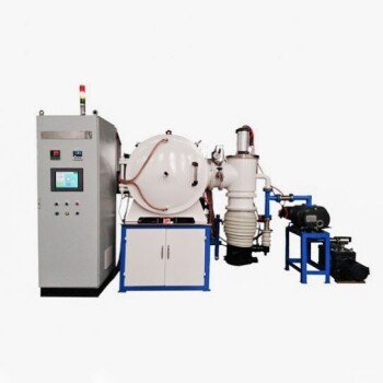
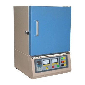
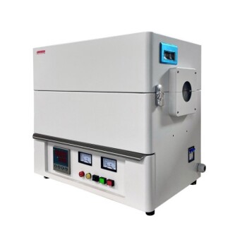
Don’t let injector failure or coking disrupt your critical operations. KINTEK provides industry-leading laboratory solutions backed by expert R&D and manufacturing. Our high-temperature systems, including Muffle, Tube, Rotary, Vacuum, and CVD furnaces, are fully customizable to meet your specific thermal and cooling requirements.
Whether you need precise boundary conditions for experimental research or robust hardware longevity for production, our engineers are ready to design the perfect system for you.
Ready to upgrade your thermal processing? Contact KINTEK today for a custom solution!
Visual Guide
References
- Garikai T. Marangwanda, Daniel M. Madyira. Evaluating Combustion Ignition, Burnout, Stability, and Intensity of Coal–Biomass Blends Within a Drop Tube Furnace Through Modelling. DOI: 10.3390/en18061322
This article is also based on technical information from Kintek Furnace Knowledge Base .
Related Products
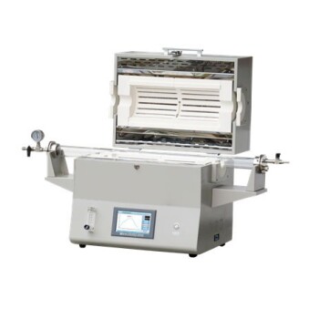
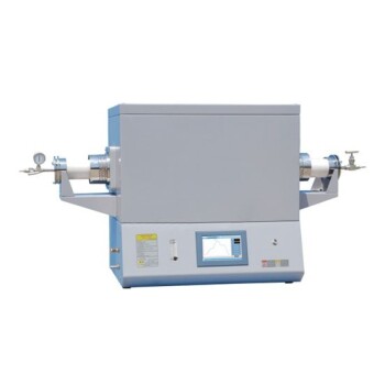
- 1400℃ High Temperature Laboratory Tube Furnace with Alumina Tube
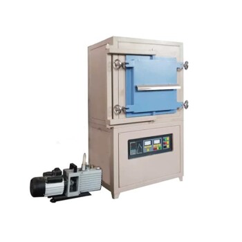
- 1700℃ Controlled Inert Nitrogen Atmosphere Furnace
- 1700℃ High Temperature Laboratory Tube Furnace with Alumina Tube
- 1700℃ High Temperature Muffle Oven Furnace for Laboratory
- 1200℃ Muffle Oven Furnace for Laboratory
People Also Ask
- How does a laboratory high-temperature tube furnace contribute to the conversion of electrospun fibers? Expert Insights
- How does a high-temperature tube furnace facilitate sulfur melt-diffusion? Precision Heating for PCFC/S Cathodes
- How do high-temperature laboratory tube furnaces ensure environmental stability? Precision Thermal Reduction Tips
- What role do high-performance box or tube furnaces play in LATP sintering? Master Densification & Ionic Conductivity
- What is the function of a furnace in CuAlMn alloy treatment? Achieve Perfect Microstructural Homogenization