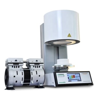
A vacuum device is critical for ensuring the optical clarity required for high-precision fluid experiments. Its primary function is to evacuate air from the container filled with acrylic packing prior to fluid injection, ensuring that even residual air trapped in microscopic gaps is completely removed.
By eliminating air bubbles, the vacuum process prevents laser scattering and reflection that would otherwise compromise image quality. This ensures that Laser-Induced Fluorescence (LIF) images remain free of shadows, allowing for accurate packing rate calculations and precise flow field measurements.
The Physics of Optical Interference
Removing Air from Microscopic Gaps
Simulated scrap steel layers, often represented by acrylic packing, create a complex structure with numerous voids.
Air naturally gets trapped in the microscopic gaps between these packing materials.
Simple fluid injection is often insufficient to displace this air. A vacuum device is required to forcefully evacuate the container before the fluid is introduced, ensuring a complete fill.
Preventing Scattering and Reflection
If air remains within the experimental layers, it interacts negatively with the diagnostic equipment.
Air bubbles cause significant laser scattering and reflection when illuminated.
This scattering disrupts the light path, preventing the laser sheet from uniformly illuminating the fluid and the packing material.
Consequences for Data Integrity
Avoiding Shadows in LIF Images
In Laser-Induced Fluorescence (LIF) techniques, clear optical access is paramount.
Scattered light from bubbles creates shadows in the resulting images.
These shadows obscure the field of view, making it impossible to distinguish between the fluid, the packing material, and the void spaces accurately.
Ensuring Measurement Accuracy
The presence of shadows and optical artifacts leads to quantitative errors.
Specifically, these artifacts result in incorrect packing rate calculations, as the software may misinterpret shadows as solid objects or voids.
Furthermore, flow field measurements become unreliable because the tracking of fluid movement is interrupted by the optical noise generated by the bubbles.
Common Pitfalls to Avoid
Relying on Fluid Displacement
A common error is assuming that the fluid injection process alone will push out all the air.
Without a vacuum, residual air bubbles invariably persist in tight geometries.
This negligence renders the resulting data prone to significant error, regardless of the quality of the camera or laser setup.
Ensuring Experimental Precision
To maximize the reliability of your fluid dynamics data, consider the following:
- If your primary focus is Image Quality: Prioritize the vacuum step to eliminate laser scattering and shadows that degrade LIF visualizations.
- If your primary focus is Quantitative Data: Use the vacuum device to ensure that packing rate and flow field measurements are not skewed by optical artifacts.
The use of a vacuum device is not merely a preparation step; it is a fundamental prerequisite for obtaining valid experimental data.
Summary Table:
| Feature | Impact of Air Bubbles | Benefit of Vacuum Device |
|---|---|---|
| Optical Clarity | Causes laser scattering and reflections | Ensures uniform laser sheet illumination |
| Image Quality | Creates shadows in LIF images | Produces clear, shadow-free visualizations |
| Data Precision | Skews packing rate calculations | Enables accurate quantitative analysis |
| Flow Analysis | Disrupts flow field measurements | Provides reliable fluid tracking data |
Elevate Your Research Precision with KINTEK
Don't let air bubbles compromise your experimental integrity. KINTEK provides high-performance vacuum systems and laboratory equipment designed to ensure the optical clarity and data accuracy your research demands. Backed by expert R&D and manufacturing, we offer customizable Vacuum systems, Muffle, Tube, Rotary, and CVD furnaces tailored to your unique fluid dynamics or high-temp needs.
Ready to eliminate optical noise and achieve superior data? Contact our experts today to find your custom solution!
References
- Manabu Tange, K. Tsutsumi. Relationship between the Nonuniformity of Packed Structure and Fluid Permeability in a Model Scrap Preheating Vessel. DOI: 10.2355/isijinternational.isijint-2023-458
This article is also based on technical information from Kintek Furnace Knowledge Base .
Related Products
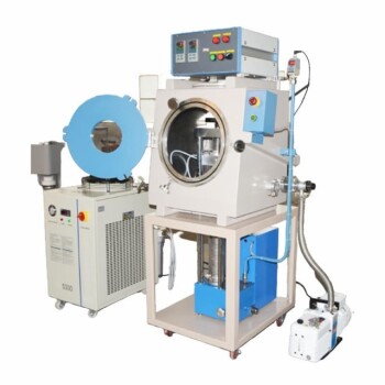
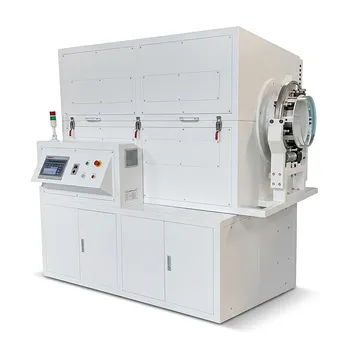
- Vacuum Hot Press Furnace Machine for Lamination and Heating
- Vacuum Hot Press Furnace Machine Heated Vacuum Press
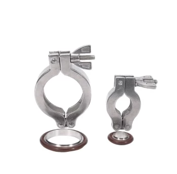
- Stainless Steel Quick Release Vacuum Chain Three Section Clamp
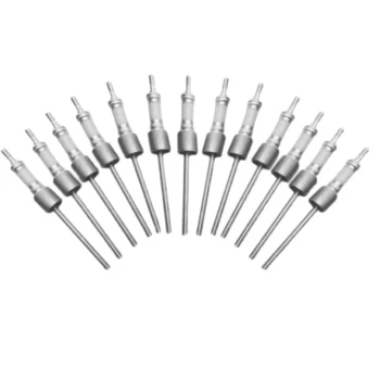
- Ultra Vacuum Electrode Feedthrough Connector Flange Power Lead for High Precision Applications
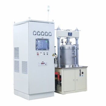
- Vacuum Hot Press Furnace Machine Heated Vacuum Press Tube Furnace
People Also Ask
- What is a vacuum hot press furnace? Unlock Superior Material Performance
- What is the primary function of the vacuum environment in a vacuum hot press furnace during titanium alloy processing? Prevent Embrittlement for Superior Ductility
- What are the benefits of the vacuum environment system in a vacuum hot press furnace? Unlock High-Density Sintering
- What safety features are incorporated in vacuum hot press furnaces? Ensure Operator and Equipment Protection
- How does a vacuum hot press furnace promote densification in the manufacturing of graphite flake/copper composites? Achieve Superior Composite Materials