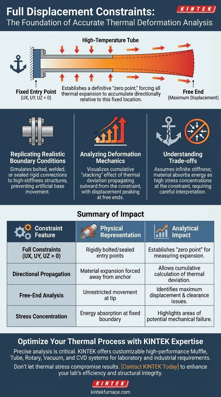
Applying full displacement constraints at fixed entry points serves as the fundamental anchor for accurate thermal simulation. By setting translation in all three axes (UX, UY, UZ) to zero, you mathematically replicate the rigid conditions where components are sealed or attached to high-stiffness structures. This establishes a definitive "zero point," forcing all thermal expansion to accumulate directionally relative to this fixed location.
Core Takeaway Full constraints are critical for calculating the realistic accumulation of thermal deformation. They reveal how thermal deviations propagate through the assembly, explaining why displacement magnitude typically peaks at the structure's free ends.
Simulating Realistic Boundary Conditions
Replicating Rigid Connections
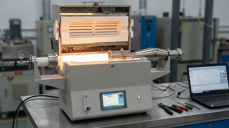
In high-temperature tube assemblies, entry points are rarely free-floating. They are typically bolted, welded, or sealed to heavier, stiffer components.
Applying full constraints (UX=UY=UZ=0) is the most accurate way to simulate this physical reality. It prevents artificial movement at the base, ensuring the simulation reflects a truly anchored system.
Defining the Structural Baseline
Without a fixed reference point, thermal deformation data lacks context.
These constraints establish the origin for the entire analysis. They define the "start" of the assembly, allowing the software to measure exactly how much the geometry deviates from its original position as heat is applied.
Analyzing Deformation Mechanics
The Accumulation of Thermal Deviation
Thermal expansion in a constrained system is cumulative.
Because the entry point cannot move, the material expansion must propagate outward. The constraints enable you to visualize this "stacking" effect, where small expansions per unit length add up to significant geometric changes over the length of the tube.
Predicting Behavior at Free Ends
The direct result of fixing the entry points is the amplification of movement at the opposite end.
The simulation will show that displacement is not uniform. Instead, it reaches its maximum at the free ends, furthest from the constraints. This insight is vital for predicting clearance issues or contact risks in the final assembly.
Understanding the Trade-offs
The Assumption of Infinite Stiffness
Applying full constraints assumes the supporting structure is infinitely rigid.
While this is often close enough for tube analysis, it is an idealization. In reality, even high-stiffness structures may flex slightly under extreme loads.
Stress Concentrations
By preventing all movement at the entry point, the simulation forces the material to absorb the energy as stress rather than motion.
This will likely show high stress concentrations at the constraint. You must discern whether these stresses are real physical risks or artifacts of the rigid boundary condition.
Making the Right Choice for Your Analysis
To maximize the value of your simulation, align your constraint strategy with your analytical goals:
- If your primary focus is visualizing total expansion: Use full constraints to clearly observe how deformation accumulates from the base to the tip.
- If your primary focus is clearance checking: rely on the data at the "free ends," as the fixed constraints ensure this is where maximum displacement will occur.
Correctly constraining the entry points transforms abstract thermal data into a predictive map of structural movement.
Summary Table:
| Constraint Feature | Physical Representation | Analytical Impact |
|---|---|---|
| Full Constraints (UX, UY, UZ = 0) | Rigidly bolted, welded, or sealed entry points | Establishes a definitive 'zero point' for measuring expansion |
| Directional Propagation | Material expansion forced away from the anchor | Allows for cumulative calculation of thermal deviation |
| Free-End Analysis | Unrestricted movement at the assembly tip | Identifies maximum displacement and potential clearance issues |
| Stress Concentration | Energy absorption at the fixed boundary | Highlights areas of potential mechanical failure under thermal load |
Optimize Your Thermal Process with KINTEK Expertise
Precise thermal deformation analysis is critical for the longevity of high-temperature equipment. Backed by expert R&D and manufacturing, KINTEK offers high-performance Muffle, Tube, Rotary, Vacuum, and CVD systems, all of which are fully customizable to meet your unique laboratory or industrial requirements.
Don't let thermal stress compromise your results. Our specialized high-temperature furnaces are designed to handle the rigorous demands of advanced thermal simulation and production. Contact KINTEK today to discover how our engineering excellence can enhance your lab's efficiency and structural integrity.
Visual Guide
References
- Nenghong Zheng, Ye Chen. Numerical Simulation Research on Screen Superheater of Supercritical Circulating Fluidized Bed Boiler. DOI: 10.54691/czsm3b20
This article is also based on technical information from Kintek Furnace Knowledge Base .
Related Products
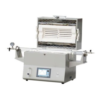
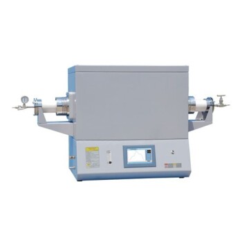
- 1400℃ High Temperature Laboratory Tube Furnace with Alumina Tube
- 1700℃ High Temperature Laboratory Tube Furnace with Alumina Tube
- 1200℃ Split Tube Furnace Laboratory Quartz Tube Furnace with Quartz Tube
- Vertical Laboratory Quartz Tube Furnace Tubular Furnace
- High Pressure Laboratory Vacuum Tube Furnace Quartz Tubular Furnace
People Also Ask
- How do high-temperature laboratory tube furnaces ensure environmental stability? Precision Thermal Reduction Tips
- How does a high-temperature tube furnace facilitate sulfur melt-diffusion? Precision Heating for PCFC/S Cathodes
- What is the mechanism of a high-temperature furnace in Bi-2223 sintering? Achieve Precision Phase Transformation
- What is a high temperature tube furnace? Achieve Precise Heat and Atmosphere Control
- In what scenarios are laboratory high-temperature tube furnaces or muffle furnaces utilized? Study MgTiO3-CaTiO3 Ceramics