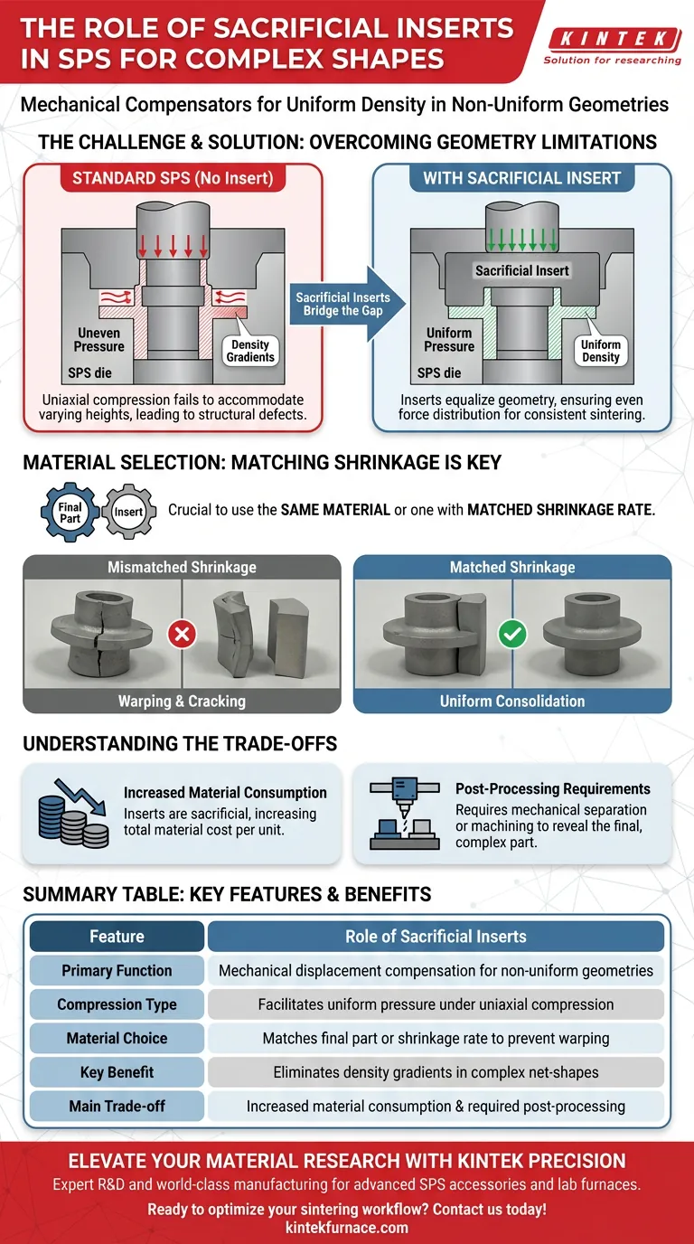
Sacrificial inserts serve as essential mechanical compensators within the Spark Plasma Sintering (SPS) process, specifically designed to enable the fabrication of components with complex, non-uniform geometries. By placing these inserts within the die, manufacturers can neutralize the displacement differences that occur during sintering, ensuring that force is distributed evenly across parts that possess varying cross-sectional thicknesses.
Standard SPS configurations often fail to produce uniform density in complex shapes because uniaxial compression cannot naturally accommodate varying heights. Sacrificial inserts bridge this gap by balancing internal forces, allowing the system to sinter complex structures with the same consistency as simple flat shapes.
Overcoming the Geometry Challenge
The Limitation of Single-Punch Systems
Standard SPS setups rely on uniaxial compression, where force is applied in a single direction.
In a simple cylinder, this works perfectly. However, if a component has a non-uniform cross-section—such as a step or a flange—a single rigid punch cannot apply equal pressure to both the thick and thin sections simultaneously.
Balancing Forces via Displacement Compensation
Sacrificial inserts function by artificially equalizing the geometry within the die.
They are positioned to fill the voids or gaps created by the complex shape of the target component. This ensures that when the punch descends, it encounters a uniform resistance across the entire surface area.
By compensating for displacement differences, the inserts prevent density gradients that would otherwise ruin the structural integrity of the part.
Material Selection Strategy
Matching Shrinkage Rates
For a sacrificial insert to function correctly, it is typically manufactured from the same material as the final part.
Alternatively, it can be made from a material that possesses a strictly matched shrinkage rate.
Ensuring Uniform Consolidation
If the insert creates a different thermal or mechanical response than the component, the part may warp or crack during the cooling phase.
Using a matching material ensures that both the insert and the component contract at the exact same rate, maintaining the dimensional accuracy of the complex shape.
Understanding the Trade-offs
Increased Material Consumption
As the name implies, these inserts are sacrificial.
They are consumed during the process to ensure the quality of the final part. This inevitably increases the total material cost per unit, as you are sintering material that will ultimately be discarded or recycled.
Post-Processing Requirements
The use of inserts introduces an additional step in the manufacturing workflow.
Once the sintering process is complete, the sacrificial section is effectively fused or pressed against the final component. This requires precise mechanical separation or machining to reveal the final, complex-shaped part.
Making the Right Choice for Your Project
While sacrificial inserts unlock the ability to sinter complex geometries, they add variables to the process. Use the following guide to determine your approach:
- If your primary focus is Structural Integrity: Ensure your insert is made from the exact same powder batch as the component to guarantee identical shrinkage rates and density distribution.
- If your primary focus is Complex Geometry: Use inserts to convert your complex, stepped design into a simple cylinder shape for the punch, ensuring the SPS machine "sees" a uniform surface.
Sacrificial inserts transform the limitations of uniaxial compression into a capability for complex net-shape manufacturing.
Summary Table:
| Feature | Role of Sacrificial Inserts |
|---|---|
| Primary Function | Mechanical displacement compensation for non-uniform geometries |
| Compression Type | Facilitates uniform pressure under uniaxial compression |
| Material Choice | Matches final part material or shrinkage rate to prevent warping |
| Key Benefit | Eliminates density gradients in complex net-shapes |
| Main Trade-off | Increased material consumption and required post-processing |
Elevate Your Material Research with KINTEK Precision
Fabricating complex-shaped components requires more than just technique—it demands the right equipment. Backed by expert R&D and world-class manufacturing, KINTEK provides advanced Spark Plasma Sintering (SPS) accessories, CVD systems, and lab high-temp furnaces (Muffle, Tube, Rotary, Vacuum) tailored to your specific research needs.
Ready to overcome geometry challenges and achieve superior structural integrity? Contact us today to discuss your customizable furnace requirements and let our experts help you optimize your sintering workflow.
Visual Guide
References
- Alexander M. Laptev, Olivier Guillon. Tooling in Spark Plasma Sintering Technology: Design, Optimization, and Application. DOI: 10.1002/adem.202301391
This article is also based on technical information from Kintek Furnace Knowledge Base .
Related Products
- Spark Plasma Sintering SPS Furnace
- 915MHz MPCVD Diamond Machine Microwave Plasma Chemical Vapor Deposition System Reactor
- RF PECVD System Radio Frequency Plasma Enhanced Chemical Vapor Deposition
- 9MPa Air Pressure Vacuum Heat Treat and Sintering Furnace
- 600T Vacuum Induction Hot Press Vacuum Heat Treat and Sintering Furnace
People Also Ask
- What is the significance of high-precision temperature monitoring systems in SPS? Control Ti-6Al-4V/HA Microstructure
- What are the key differences between SiC and MoSi2 heating elements in sintering furnaces? Choose the Right Element for Your High-Temp Needs
- What are the steps in the discharge plasma sintering process? Master Fast, High-Density Material Consolidation
- What is unique about the heating mechanism of a Spark Plasma Sintering (SPS) furnace when preparing nanostructured h-BN ceramics? Achieve Ultra-Fast Densification and Suppress Grain Growth
- What are the technical advantages of using an SPS sintering furnace? Elevate Al2O3-TiC Material Performance