Cracking is fundamentally caused by the development of capillary-stress-driven biaxial tensile forces as the liquid evaporates from the pore network while the film is rigidly adhered to a non-shrinking substrate. Failure occurs when the film thickness exceeds the critical cracking thickness (CCT), the point at which the strain energy released by crack propagation surpasses the fracture energy of the weak, unfired body.
The root cause of drying cracks is a mechanical energy imbalance driven by capillary pressure, not thermal expansion. Preventing cracking requires either reducing the tensile stress generated during drying or increasing the strength of the fragile green film. The primary levers are particle size optimization, solvent selection, colloidal stability control, and binder addition.
The Root Cause: Capillary Stress in a Constrained Film
The physics of drying failure in a green ceramic film is distinct from the sintering cracks and dewetting phenomena that occur later in a high-temperature furnace. The damage happens at ambient or slightly elevated temperatures, long before the material ever sees a sintering profile.
The Mechanical Problem of Substrate Constraint
A wet ceramic film cast on a rigid substrate undergoes volumetric shrinkage solely in the thickness direction as liquid evaporates.
The rigid substrate prevents any lateral contraction. This constraint forces the film into a state of biaxiaxial tensile stress. Think of it like a stretched drumhead. The material wants to pull inwards from all sides but is locked in place, putting it under constant tension.
The Role of Capillary Tension in the Pores
The tensile stress is generated by the liquid-vapor menisci that form in the pores between ceramic particles near the drying surface.
As liquid recedes, these menisci create a negative capillary pressure ((P_{cap})) in the pore fluid. This pressure pulls the solid particles together. The resulting tensile stress in the particle network ((σ_x)) is proportional to this pressure and can be approximated by (σ_x ≈ (2γ_{LV} cosθ) / a), where (γ_{LV}) is the liquid surface tension, (θ) is the contact angle, and (a) is the pore radius. Smaller pores generate drastically higher destructive stresses.
How to Increase the Critical Cracking Thickness
To raise the CCT and build thicker, crack-free films, you must manipulate the formulation variables that govern this capillary stress or the body's resistance to it.
Enlarging Primary Particle Size
Using a larger starting ceramic particle size is the most direct method to lower the capillary stress.
Larger particles naturally pack to form larger inter-particle pores (a larger pore radius (a)) . Referring back to the capillary stress equation, a larger pore radius mathematically reduces the tensile stress for the same liquid. By reducing the peak stress, the film can be cast thicker before the catastrophic energy-release threshold is met.
Reducing the Liquid Surface Tension
You can attack the problem by changing the liquid phase rather than the solid phase.
By selecting a solvent or adding an additive that has a lower surface tension ((γ_{LV})) , you directly reduce the magnitude of the capillary pressure pulling the particles together. This is a common and highly effective strategy to delay the onset of cracking during drying prior to furnace processing.
Strengthening the Green Network with Binders
Rather than lowering the stress, this strategy increases the material's ability to withstand it.
Adding organic binders reinforces the fragile network of ceramic particles. A flexible binder bridges between particles, significantly increasing the tensile strength and fracture toughness of the green body. A stronger film can dissipate more strain energy before a flaw propagates, directly increasing the CCT without changing the capillary physics.
Manipulating Colloidal Stability
The state of particle dispersion is a powerful but nuanced control variable.
A flocculated (agglomerated) suspension dramatically increases the CCT compared to a fully dispersed one. The flocculated particle clusters create a heterogeneous pore structure with large, stress-relieving inter-aggregate voids alongside the smaller intra-aggregate pores. These larger voids lower the average capillary stress and disrupt crack propagation paths.
Understanding the Trade-offs
There are no silver bullets. The strategies to increase CCT often come with direct penalties for the film's final quality after high-temperature furnace sintering. An objective choice requires understanding these conflicts.
The Packing Density vs. Crack Resistance Problem
The most significant trade-off lies with flocculated suspensions.
While a flocculated state greatly increases CCT, it does so at the expense of green packing density. The same large voids that relieve stress also prevent a tight particle arrangement. A low green density makes it harder to achieve full densification in the subsequent furnace sintering step, potentially leading to lower final strength, higher porosity, and other microstructural defects.
Organic Burnout Considerations
The binders that provide critical green strength must be completely removed before sintering in a high-temperature furnace.
This requires a slow, controlled binder burnout cycle at intermediate temperatures. If not performed correctly, the rapid decomposition of the binder can create internal gas pressure that disrupts the particle packing or leaves behind carbon residue, both of which compromise the final sintered microstructure.
How to Design a Crack-Free Drying Protocol
Your specific formulation goals will determine the optimal path. Consider these decision paths when tackling a cracking problem before the material goes into the sintering furnace.
- If your primary focus is a defect-free, thick film for a structural application: Increase particle size and use a controlled flocculated suspension, but be aware you will need to design a high-temperature furnace sintering cycle that compensates for a low initial packing density.
- If your primary focus is achieving a dense, fine-grained final microstructure: Use a well-dispersed suspension with ultrafine particles and focus your efforts on lowering liquid surface tension and adding a high-strength organic binder to manage capillary stress.
- If your primary focus is eliminating a new cracking problem in an established process: First, evaluate your drying environment. A process control strategy using high-humidity, slightly elevated temperature (~70°C) drying can reduce evaporation gradients and liquid viscosity, providing a path to cracking relief without any change to the ceramic slurry formulation.
By systematically addressing the capillary stress magnitude and the green body's fracture resistance, you can engineer a reliable drying protocol that delivers intact films to the sintering furnace.
Summary Table:
| Strategy | Mechanism to Increase CCT | Primary Trade-off / Consideration |
|---|---|---|
| Enlarge Particle Size | Increases pore radius ($a$), directly reducing capillary stress ($P_{cap}$) | May require adjusted sintering profiles to reach full density |
| Reduce Surface Tension | Lowers liquid surface tension ($\gamma_{LV}$), reducing capillary pressure | Requires careful solvent or surfactant selection |
| Add Organic Binders | Strengthens particle network, increasing green fracture toughness | Demands controlled binder burnout cycle before sintering |
| Control Flocculation | Introduces larger inter-aggregate voids to relieve tensile stress | Lowers initial green packing density |
Optimize Ceramic Sintering and Defect-Free Processing with KINTEK
Navigating green film drying, binder burnout, and high-temperature sintering requires precise thermal control and robust equipment. At KINTEK, we specialize in premium laboratory equipment and consumables engineered to support advanced ceramic research and production.
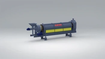
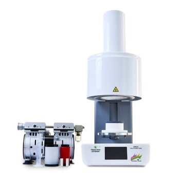
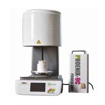
From precise atmosphere control to customized heating profiles, our full range of high-temperature furnaces—including muffle, tube, rotary, vacuum, CVD, atmosphere, dental, and induction melting furnaces—can be tailored to meet your exact processing needs.
Ready to elevate your ceramic processing performance? Contact us today to discuss your custom furnace solution with a KINTEK specialist!
Related Products
- Multi Heating Zones CVD Tube Furnace Machine for Chemical Vapor Deposition Equipment
- Custom Made Versatile CVD Tube Furnace Chemical Vapor Deposition CVD Equipment Machine
- Inclined Rotary Plasma Enhanced Chemical Deposition PECVD Tube Furnace Machine
- High Temperature Muffle Oven Furnace for Laboratory Debinding and Pre Sintering
- 915MHz MPCVD Diamond Machine Microwave Plasma Chemical Vapor Deposition System Reactor
People Also Ask
- What is the function of a multi-zone tube furnace in CVD synthesis? Master 2D In2Se3 Nanosheet Precision
- What temperature-related capabilities make multi zone tube furnaces valuable for research? Unlock Precision Thermal Control
- Why are multi zone tube furnaces particularly useful for nanomaterial research? Unlock Precise Thermal Control for Advanced Synthesis
- What environmental protection applications utilize multi zone tube furnaces? Unlock Precision in Waste Treatment and Green Tech
- What role do multi zone tube furnaces play in new energy research? Unlock Precise Thermal Control for Innovation