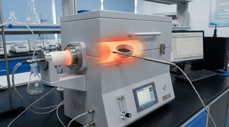
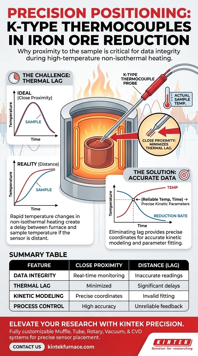
Precise sensor placement is mandatory for data integrity in iron ore reduction experiments. Placing the K-type thermocouple in immediate proximity to the sample allows for the real-time monitoring of the actual reduction temperature. This close positioning is the primary defense against thermal lag, ensuring that the recorded data accurately reflects the thermal energy the sample is absorbing.
In high-frequency non-isothermal heating, distance introduces delay. Minimizing the gap between the sensor and the sample eliminates thermal lag, providing the precise temperature coordinates necessary for accurately calculating reduction kinetic parameters.
The Challenge of Non-Isothermal Heating
Dealing with Rapid Temperature Changes
Iron ore reduction experiments often utilize high-frequency non-isothermal heating. Unlike steady-state heating, this method involves rapid changes in temperature over time.
Because the thermal environment is dynamic, the temperature of the furnace atmosphere may differ significantly from the temperature of the sample itself at any given second.
Eliminating Thermal Lag
If the thermocouple is positioned even a small distance away from the sample, a phenomenon known as thermal lag occurs.
This results in a delay between when the sample reaches a specific temperature and when the sensor records it. By placing the thermocouple extremely close to the sample, you minimize this time delay and capture the true thermal profile.
The Impact on Kinetic Modeling
Securing Reliable Temperature Coordinates
For scientific analysis, you need a reliable temperature coordinate to correlate with the reduction rate.
If the temperature data is skewed by lag, your data points will be shifted on the time axis. This makes it impossible to determine exactly what temperature triggered a specific chemical change in the ore.
Accurate Parameter Fitting
The ultimate goal of these experiments is often to fit reduction kinetic parameters.
These mathematical models rely on precise inputs. If the temperature input is flawed due to poor sensor positioning, the calculated kinetic parameters will be incorrect, rendering the model invalid for predicting real-world behavior.
Understanding the Trade-offs
Proximity vs. Interference
While closeness is critical for accuracy, it introduces physical challenges.
You must ensure the thermocouple is close enough to read the sample's heat but positioned so it does not mechanically interfere with the sample's expansion or contraction during reduction.
Sensor Limitations
K-type thermocouples are robust, but they measure point-specific data.
In extremely large samples, a single point of measurement near the surface may not represent the internal core temperature perfectly. However, for the purpose of kinetic fitting in controlled experiments, the surface proximity remains the standard for minimizing external environmental errors.
Ensuring Experimental Integrity
To derive meaningful data from your iron ore reduction process, precise setup is as important as the heating method itself.
- If your primary focus is Kinetic Modeling: Prioritize minimizing the gap between sensor and sample to ensure your mathematical parameter fitting is based on lag-free data.
- If your primary focus is Process Control: Ensure the thermocouple is fixed securely so that high-frequency vibrations do not alter the distance during the experiment.
Accurate positioning transforms your data from a rough estimate into a reliable scientific standard.
Summary Table:
| Feature | Impact of Close Proximity | Consequence of Distance (Lag) |
|---|---|---|
| Data Integrity | Real-time monitoring of sample temp | Inaccurate furnace-only temperature readings |
| Thermal Lag | Minimized; matches heating rate | High; introduces significant time delays |
| Kinetic Modeling | Precise temperature-time coordinates | Skewed data points; invalid parameter fitting |
| Process Control | High-frequency heating accuracy | Unreliable feedback loop for rapid changes |
Elevate Your Materials Research with KINTEK Precision
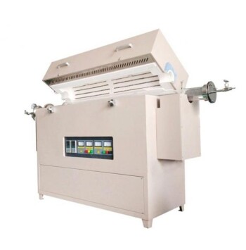
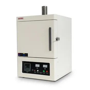
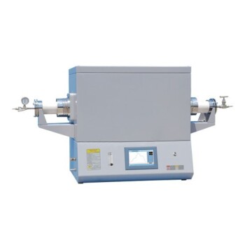
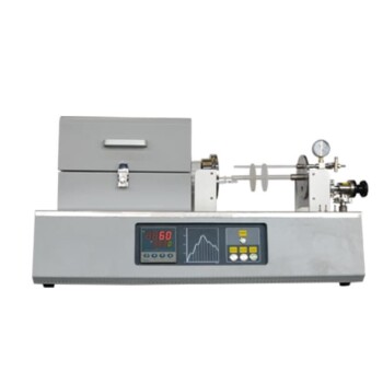
Don't let thermal lag compromise your kinetic modeling. At KINTEK, we understand that experimental integrity starts with the right equipment and precise control. Backed by expert R&D and manufacturing, we offer high-performance Muffle, Tube, Rotary, Vacuum, and CVD systems, all of which are fully customizable to accommodate precise sensor positioning and your unique iron ore reduction requirements.
Ready to optimize your high-temperature processes? Contact us today to discover how our customizable lab furnaces can provide the accuracy your research demands.
Visual Guide
References
- Yuzhao Wang, Samuli Urpelainen. In Situ SXRD Study of Phase Transformations and Reduction Kinetics in Iron Ore During Hydrogen-Based High-Temperature Reduction. DOI: 10.1007/s11663-025-03725-2
This article is also based on technical information from Kintek Furnace Knowledge Base .
Related Products
- Multi Heating Zones CVD Tube Furnace Machine for Chemical Vapor Deposition Equipment
- High Temperature Muffle Oven Furnace for Laboratory Debinding and Pre Sintering
- Multi Zone Laboratory Quartz Tube Furnace Tubular Furnace
- Vertical Laboratory Quartz Tube Furnace Tubular Furnace
- 1200℃ Muffle Oven Furnace for Laboratory
People Also Ask
- What are the benefits of integrating multiple heating zones in a tube furnace? Unlock Precise Thermal Control
- What role does a Tube Furnace play in the CVD growth of carbon nanotubes? Achieve High-Purity CNT Synthesis
- What are the advantages of multi-zone tube furnaces? Achieve Superior Thermal Control for Advanced Materials Processing
- What environmental protection applications utilize multi zone tube furnaces? Unlock Precision in Waste Treatment and Green Tech
- What are the main applications of multi zone tube furnaces in university laboratories? Unlock Precision in Material Science and Energy Research