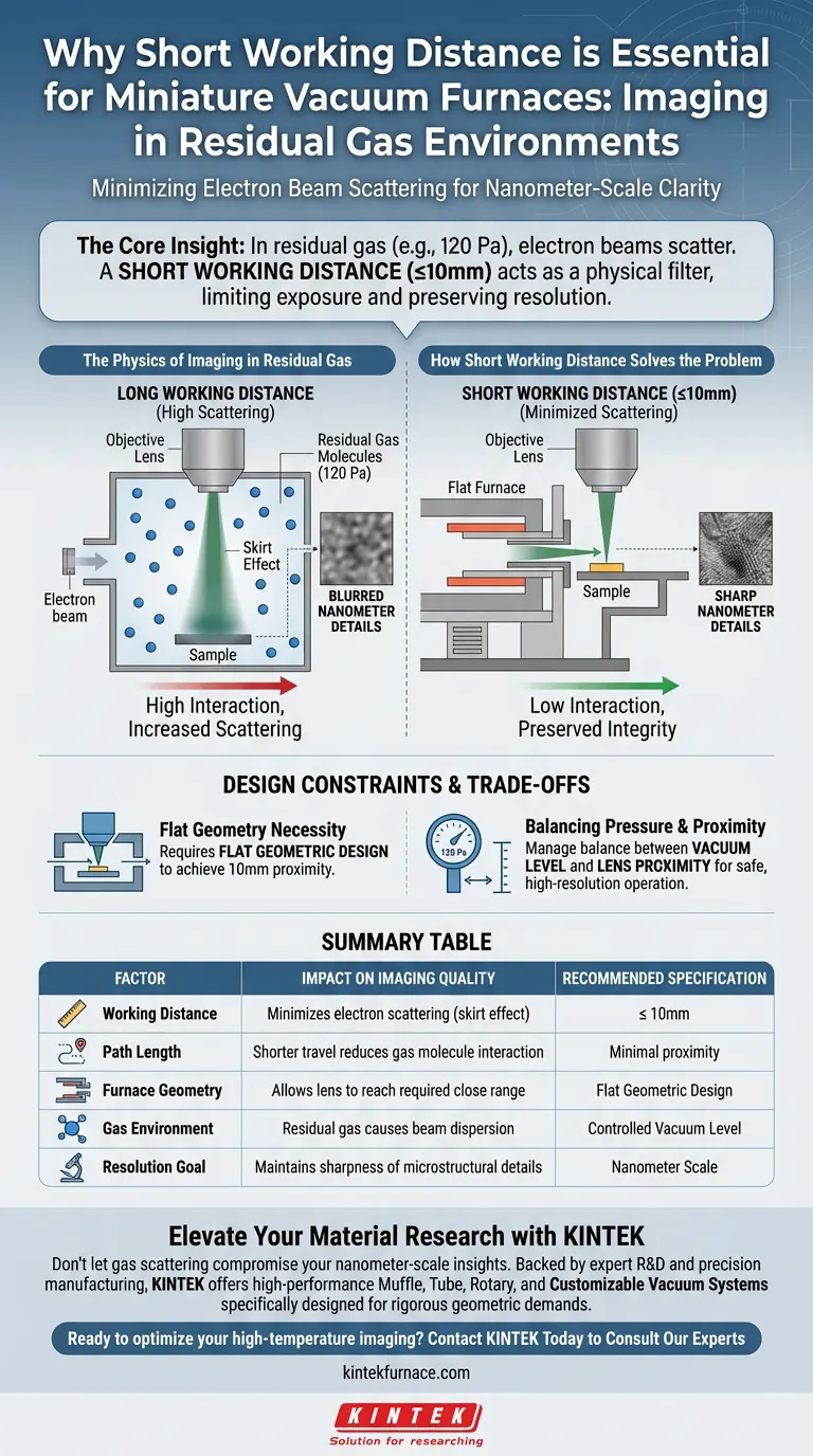
A short working distance is critical for imaging in miniature vacuum furnaces because it minimizes the interaction between the electron beam and gas molecules. By reducing the distance the beam travels—ideally to 10mm or less—you significantly lower the rate of electron scattering, preserving the clarity of nanometer-scale microstructural details even in residual gas environments.
The Core Insight In environments with residual gas (such as 120 Pa), electron beams naturally disperse upon contact with gas molecules, reducing image sharpness. A short working distance acts as a physical filter, limiting the beam's exposure to the gas and preventing the loss of resolution caused by scattering.
The Physics of Imaging in Residual Gas
The Challenge of Gas Molecules
When performing imaging in a vacuum furnace, you are often working in residual gas environments, sometimes around 120 Pa.
Unlike a high vacuum, this environment contains a significant number of gas molecules floating in the chamber.
The "Skirt Effect" Phenomenon
As the electron beam travels from the source to the sample, it collides with these gas molecules.
This interaction causes the electrons to scatter, a phenomenon technically referred to as the skirt effect.
Instead of a focused point, the beam spreads out, which directly degrades the resolution of the final image.
How Short Working Distance Solves the Problem
Minimizing Path Length
The most effective way to counter the skirt effect is to reduce the physical distance the electron beam must travel.
By shortening the working distance, you minimize the "path length" through the gas.
Preserving Beam Integrity
With a shorter path, the electron beam encounters fewer gas molecules before it hits the sample.
This results in less scattering and maintains a tighter, more focused beam.
Achieving Nanometer Resolution
When the working distance is reduced to 10mm or less, the impact of the gas is negligible enough to allow for high-precision imaging.
This proximity ensures that nanometer-scale microstructural details remain sharp and distinct, rather than blurred.
Design Constraints and Trade-offs
The Necessity of Flat Geometry
Achieving a 10mm working distance is not possible with standard, bulky furnace designs.
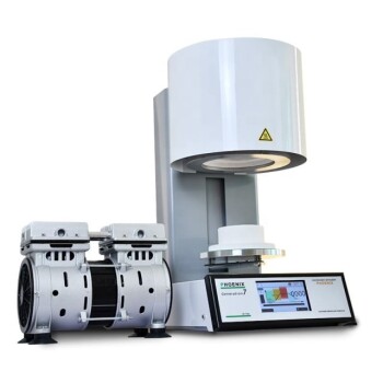
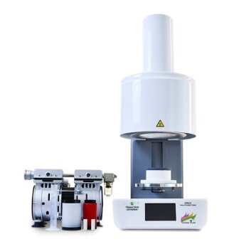
Miniature vacuum furnaces must utilize a flat geometric design to physically allow the objective lens to get close enough to the sample.
Balancing Pressure and Proximity
While a short working distance mitigates scattering, it does not eliminate the presence of gas.
Operators must still manage the balance between the vacuum level (pressure) and the proximity of the lens to ensure the equipment operates safely while maximizing resolution.
Making the Right Choice for Your Goal
To ensure you capture the necessary microstructural data, apply these principles to your setup:
- If your primary focus is maximizing image resolution: Ensure your experimental setup allows for a working distance of 10mm or less to mitigate the skirt effect.
- If your primary focus is equipment selection: Prioritize miniature vacuum furnaces with flat geometric designs, as this physical profile is required to achieve the necessary proximity.
Minimizing the gap between lens and sample is the definitive factor in overcoming gas scattering for clear, nanoscale imaging.
Summary Table:
| Factor | Impact on Imaging Quality | Recommended Specification |
|---|---|---|
| Working Distance | Minimizes electron scattering (skirt effect) | $\le$ 10mm |
| Path Length | Shorter travel reduces gas molecule interaction | Minimal proximity |
| Furnace Geometry | Allows lens to reach required close range | Flat Geometric Design |
| Gas Environment | Residual gas at ~120 Pa causes beam dispersion | Controlled Vacuum Level |
| Resolution Goal | Maintains sharpness of microstructural details | Nanometer Scale |
Elevate Your Material Research with KINTEK
Don’t let gas scattering compromise your nanometer-scale insights. Backed by expert R&D and precision manufacturing, KINTEK offers high-performance Muffle, Tube, Rotary, and Customizable Vacuum Systems specifically designed to meet the rigorous geometric demands of high-resolution imaging.
Whether you need standard lab equipment or a bespoke furnace for unique environmental challenges, our team provides the technical expertise to ensure your setup delivers maximum clarity and durability.
Ready to optimize your high-temperature imaging? Contact KINTEK Today to Consult Our Experts
Visual Guide
References
- Jérôme Mendonça, Renaud Podor. Development of a microfurnace dedicated to <i>in situ</i> scanning electron microscope observation up to 1300 °C. III. <i>In situ</i> high temperature experiments. DOI: 10.1063/5.0207477
This article is also based on technical information from Kintek Furnace Knowledge Base .
Related Products
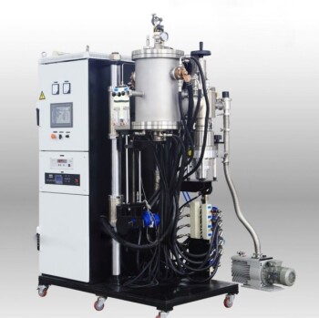
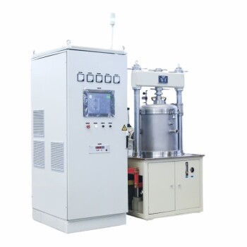
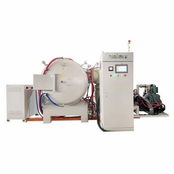
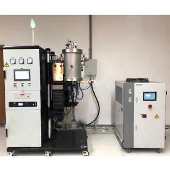
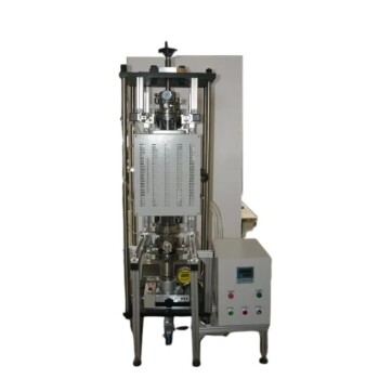
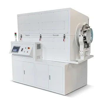
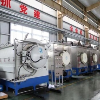
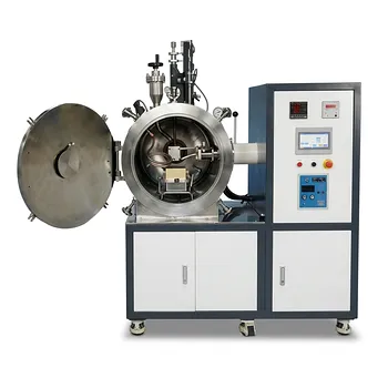
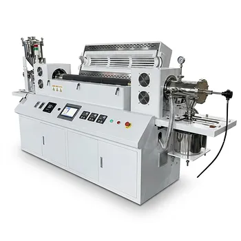
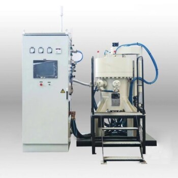
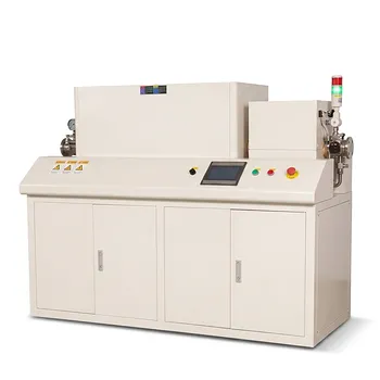
- Small Vacuum Heat Treat and Tungsten Wire Sintering Furnace
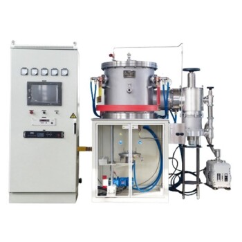
- Vacuum Heat Treat Sintering Furnace with Pressure for Vacuum Sintering
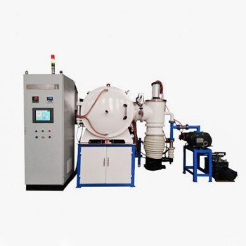
- Vacuum Hot Press Furnace Machine Heated Vacuum Press
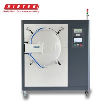
- Molybdenum Vacuum Heat Treat Furnace
- Vacuum Heat Treat Sintering Furnace Molybdenum Wire Vacuum Sintering Furnace
People Also Ask
- What role do vacuum sintering furnaces play in additive manufacturing? Transform 3D Prints into Dense, High-Performance Parts
- What are the key components of a vacuum sintering furnace? Essential Parts for Precision Material Processing
- What is the purpose of a vacuum sintering furnace? Create High-Performance Parts with Superior Purity
- What types of materials are suitable for vacuum sintering furnaces? Ideal for Reactive Metals and High-Purity Applications
- How does vacuum sintering improve material properties? Boost Strength, Purity, and Performance