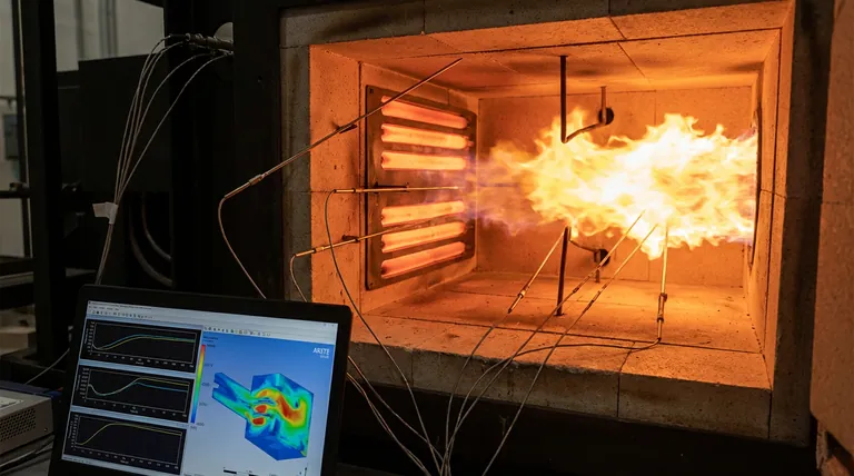
The strategic placement of thermocouples provides the empirical foundation necessary to bridge the gap between theoretical simulations and physical reality. By positioning sensors within specific reaction zones, researchers generate real-time temperature profiles that serve as a direct benchmark for Computational Fluid Dynamics (CFD) simulations. This allows for the precise verification of predicted temperature fields, ensuring that models accurately capture critical phenomena such as high-temperature peaks—which can exceed 2100 K—and localized heat dissipation.
Core Takeaway: Strategic thermocouple placement enables the validation of combustion models by providing zone-specific data that distinguishes between chemical heat release, phase changes, and environmental heat loss. This granular approach transforms raw temperature data into a robust tool for refining CFD accuracy and heat balance calculations.
Mapping the Thermal Landscape of the Reactor
Verifying High-Temperature Peak Distributions
Placing thermocouples in primary oxidation and reduction zones allows for the capture of maximum gas-phase temperatures. These readings act as a critical "truth" for CFD models, confirming whether the simulation correctly predicts the location and intensity of high-temperature peaks.
Evaluating Boundary Heat Dissipation
Sensors placed near the chamber walls are essential for measuring energy lost to the surrounding environment. This data ensures that the combustion model does not over-predict efficiency by failing to account for real-world heat dissipation and thermal conductivity of the reactor materials.
Capturing Real-Time Temperature Profiles
Continuous data collection during a burn provides a temporal map of the combustion event. This allows researchers to compare the speed of the flame front and the rate of temperature rise against the model’s predicted kinetic rates.
Constructing a Comprehensive Heat Balance Model
Distinguishing Between Energy Sources
A differentiated sensor arrangement allows researchers to isolate the thermal impact of the ignition source from the heat released by the combustion itself. This prevents the model from incorrectly attributing electrical ignition energy to the chemical energy density of the fuel.
Accounting for Phase Change Energy
In metal combustion, such as magnesium, significant energy is consumed during phase changes (melting and vaporization). Strategically placed probes help quantify this energy "sink," ensuring the model accounts for latent heat rather than just sensible heat changes.
Isolating Fluctuations in the Gas Phase
Probes located near the ignition resistance wire provide a baseline for the maximum gas-phase temperature. This data is vital for validating models that simulate the complex interaction between solid-phase heating and gas-phase oxidation.
Understanding the Trade-offs and Limitations
Sensor Interference and Flow Disturbance
While more sensors provide more data, each physical probe can potentially disrupt the flow field or act as a heat sink. This interference can introduce small errors into the very temperature profiles the sensors are meant to validate.
Spatial Resolution Constraints
Thermocouples provide discrete point measurements rather than a continuous visual field. A model may predict a peak between two sensors that is never captured, leading to a "false negative" during the validation process if the placement is not mathematically optimized.
Radiation and Response Time Errors
At temperatures near 2100 K, radiation errors can significantly affect thermocouple accuracy. High-velocity combustion events may also exceed the thermal lag of the sensor, meaning the model might appear faster or more reactive than the recorded data suggests.
How to Apply Sensor Strategy to Your Validation Goal
Making the Right Choice for Your Goal
To maximize the utility of your experimental data, sensor placement must align with the specific aspect of the model you intend to validate.
- If your primary focus is CFD Accuracy: Place sensors at the exact coordinates of predicted thermal peaks to verify the model’s spatial precision.
- If your primary focus is Energy Efficiency: Focus on wall-mounted sensors and exhaust ports to create a closed-loop heat balance calculation.
- If your primary focus is Ignition Kinetics: Position high-response probes near the ignition source to capture the transition from external heating to self-sustained combustion.
The value of a combustion model is only as high as the experimental data used to prove it reflects the physical world.
Summary Table:
| Validation Metric | Thermocouple Placement Strategy | Key Data Provided |
|---|---|---|
| CFD Spatial Accuracy | Primary oxidation & reduction zones | Verification of high-temperature peaks (>2100 K) |
| Energy Efficiency | Near chamber walls & exhaust ports | Measurement of boundary heat dissipation & energy loss |
| Ignition Kinetics | Proximal to ignition source | Distinction between electrical energy & chemical heat release |
| Phase Transitions | Near reacting material (e.g., Magnesium) | Quantification of latent heat vs. sensible heat changes |
| Temporal Dynamics | High-response gas-phase probes | Rate of flame front propagation and kinetic speed |
Precision Thermal Solutions for Research and Industry
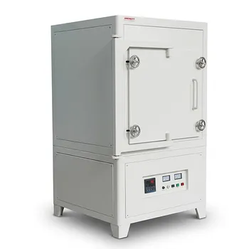
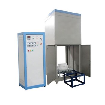
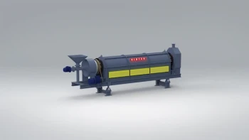
Validation of complex combustion models requires more than just data—it requires high-performance hardware capable of withstanding extreme thermal landscapes. Backed by expert R&D and manufacturing, KINTEK offers a comprehensive range of high-temperature equipment, including Muffle, Tube, Rotary, Vacuum, and CVD systems, all of which are fully customizable to meet your unique experimental needs.
Whether you are refining CFD simulations or scaling industrial combustion processes, our specialized laboratory furnaces provide the stability and control necessary for precise empirical benchmarks. Contact KINTEK today to discuss your specific requirements and learn how our advanced thermal systems can enhance your research accuracy and efficiency.
References
- Bidhan Nath, Raid Ahmed Mahmood. CFDs Modeling and Simulation of Wheat Straw Pellet Combustion in a 10 kW Fixed-Bed Downdraft Reactor. DOI: 10.3390/pr12050863
This article is also based on technical information from Kintek Furnace Knowledge Base .
Related Products
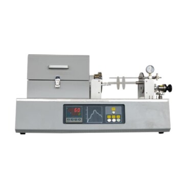
- Multi Heating Zones CVD Tube Furnace Machine for Chemical Vapor Deposition Equipment
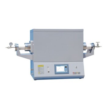
- Multi Zone Laboratory Quartz Tube Furnace Tubular Furnace
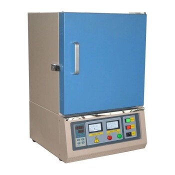
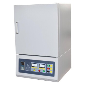
- High Temperature Muffle Oven Furnace for Laboratory Debinding and Pre Sintering
- Vertical Laboratory Quartz Tube Furnace Tubular Furnace
- Split Multi Heating Zone Rotary Tube Furnace Rotating Tube Furnace
People Also Ask
- What role does a Tube Furnace play in the CVD growth of carbon nanotubes? Achieve High-Purity CNT Synthesis
- What role do multi zone tube furnaces play in new energy research? Unlock Precise Thermal Control for Innovation
- What environmental protection applications utilize multi zone tube furnaces? Unlock Precision in Waste Treatment and Green Tech
- What temperature-related capabilities make multi zone tube furnaces valuable for research? Unlock Precision Thermal Control
- What are the main applications of multi zone tube furnaces in university laboratories? Unlock Precision in Material Science and Energy Research