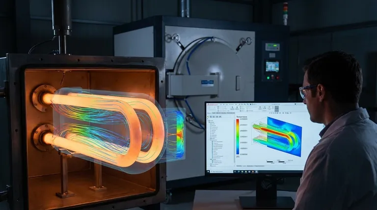
Computational Fluid Dynamics (CFD) serves as a virtual laboratory for industrial radiant tubes, enabling the creation of precise three-dimensional numerical models to simulate complex internal environments. By quantifying combustion flow fields, temperature distributions, and NOx generation, this technology allows engineers to optimize nozzle structures and flow conditions scientifically, eliminating the need for costly physical prototypes.
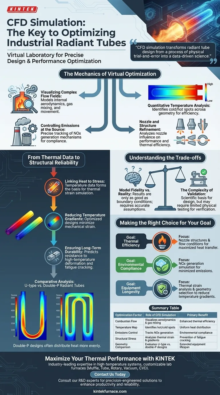
CFD simulation transforms radiant tube design from a process of physical trial-and-error into a data-driven science. It simultaneously addresses thermal efficiency and structural integrity, ensuring that designs maximize heat transfer while minimizing the thermal stresses that lead to equipment failure.
The Mechanics of Virtual Optimization
Visualizing Complex Flow Fields
CFD software builds a digital twin of the radiant tube to visualize combustion flow fields that are impossible to see in operation.
It models how gases move and mix within the tube, providing a granular view of internal aerodynamics.
Quantitative Temperature Analysis
The simulation provides a detailed map of temperature distribution across the entire geometry of the tube.
This allows designers to identify cold spots that reduce efficiency or hot spots that risk material failure.
Controlling Emissions at the Source
CFD allows for the precise tracking of NOx generation mechanisms during the combustion process.
By adjusting design parameters virtually, engineers can tune the system to meet strict environmental emission standards before metal is ever cut.
Nozzle and Structure Refinement
Engineers can quantitatively analyze how different nozzle structures influence the overall performance.
This facilitates the comparison of various flow conditions to determine the exact configuration that yields the highest thermal efficiency.
From Thermal Data to Structural Reliability
Linking Heat to Stress
The temperature data derived from CFD is the foundation for thermal strain simulation analysis.
Operating at high temperatures creates significant physical stress on radiant tubes; CFD identifies exactly where these stresses concentrate.
Reducing Temperature Gradients
Optimized designs aim to achieve smaller temperature gradients, which directly correlates to lower mechanical strain.
Comparative analysis—such as evaluating U-type versus double-P radiant tubes—demonstrates how specific geometries distribute heat more evenly.
Ensuring Long-Term Durability
By minimizing strain values, the simulation predicts the equipment's ability to resist high-temperature deformation.
This predictive capability is crucial for preventing fatigue cracking, thereby ensuring the long-term reliability and safety of the industrial equipment.
Understanding the Trade-offs
Model Fidelity vs. Reality
While CFD eliminates the need for initial physical prototypes, the results are only as good as the boundary conditions defined by the user.
Inaccurate assumptions regarding fuel composition or ambient conditions can lead to models that do not reflect real-world performance.
The Complexity of Validation
Simulation provides a scientific basis for design, but it does not completely replace the need for final validation.
Complex combustion behaviors may still require limited physical testing to verify the nuanced findings of the numerical model.
Making the Right Choice for Your Goal
To effectively utilize CFD in your radiant tube projects, align the simulation focus with your specific engineering objectives:
- If your primary focus is Thermal Efficiency: Prioritize the analysis of nozzle structures and flow conditions to maximize heat transfer and optimize combustion flow fields.
- If your primary focus is Environmental Compliance: Concentrate on the simulation of NOx generation to adjust combustion parameters for minimized emissions.
- If your primary focus is Equipment Longevity: Focus on thermal strain analysis to identify stress concentrations and select geometries (like double-P) that reduce temperature gradients.
By leveraging CFD, you move beyond guessing and gain the ability to engineer radiant tubes that are efficiently cleaner and structurally sound.
Summary Table:
| Optimization Factor | Role of CFD Simulation | Primary Benefit |
|---|---|---|
| Combustion Flow | Visualizes aerodynamics and gas mixing | Enhanced thermal efficiency |
| Temperature Map | Identifies hot spots and cold spots | Uniform heat distribution |
| Emissions Control | Tracks and predicts NOx generation | Environmental compliance |
| Structural Stress | Analyzes thermal strain and gradients | Prevention of fatigue cracking |
| Geometry Comparison | Evaluates U-type vs. double-P designs | Extended equipment lifespan |
Maximize Your Thermal Performance with KINTEK
Don’t leave your industrial heating efficiency to chance. KINTEK’s industry-leading expertise in high-temperature systems combines advanced design principles with robust manufacturing. Whether you need Muffle, Tube, Rotary, Vacuum, or CVD systems, our lab furnaces are fully customizable to solve your most complex thermal challenges.
Ready to optimize your heat treatment process? Contact us today to consult with our R&D experts and discover how our precision-engineered solutions can enhance your laboratory's productivity and equipment reliability.
Visual Guide
References
- Chien-Cheng Lin, Chien-Hsiung Tsai. Simulation of Staged Combustion Function in Double P-Type Radiant Tubes. DOI: 10.3390/engproc2025092094
This article is also based on technical information from Kintek Furnace Knowledge Base .
Related Products
- Vacuum Sealed Continuous Working Rotary Tube Furnace Rotating Tube Furnace
- Laboratory Quartz Tube Furnace RTP Heating Tubular Furnace
- Custom Made Versatile CVD Tube Furnace Chemical Vapor Deposition CVD Equipment Machine
- Laboratory Vacuum Tilt Rotary Tube Furnace Rotating Tube Furnace
- Magnesium Extraction and Purification Condensing Tube Furnace
People Also Ask
- What are the two main types of rotary tube furnaces based on capacity? Choose the Right One for Your Lab or Production
- What are the key advantages of using a rotary tube furnace? Achieve Dynamic, Uniform Heating for Powders
- How does the amount of material processed vary between batch and continuous rotary tube furnaces? Scale Your Production Efficiently
- What are the advantages of rotary tube furnaces in fuel compatibility? Boost Efficiency and Cut Costs
- What are the technical advantages of using a rotary tube furnace for hydrochar activation? Achieve Superior Porosity