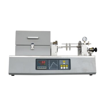
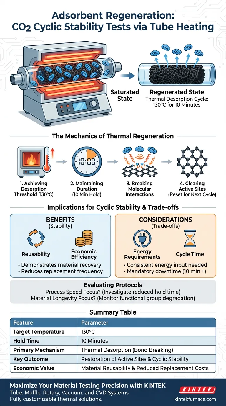
A tube heating system achieves adsorbent regeneration by subjecting the saturated material to a precise thermal desorption cycle. The system heats the sample to 130°C and maintains this temperature for a duration of 10 minutes, effectively releasing captured CO2 and resetting the material for subsequent use.
The core mechanism of regeneration is the application of heat to break the interactions between CO2 molecules and the carbon surface functional groups. This controlled thermal cycling demonstrates the material's reusability and economic viability for industrial applications.
The Mechanics of Thermal Regeneration
Achieving the Desorption Threshold
The tube heating system is designed to reach a specific target temperature of 130°C. This thermal elevation is the primary driver for the regeneration process.
The Importance of Duration
Once the target temperature is reached, the system maintains thermal stability for exactly 10 minutes. This holding period is critical to ensure the desorption process is comprehensive throughout the sample.
Breaking Molecular Interactions
The application of heat targets the specific bonds formed during adsorption. The thermal energy breaks the interactions between the CO2 molecules and the functional groups on the carbon surface.
Clearing Active Sites
By severing these bonds, the system physically releases the CO2 from the material. This clears the active sites on the adsorbent, returning it to a pristine state ready for a new adsorption cycle.
Implications for Cyclic Stability
Demonstrating Reusability
The ability to successfully regenerate the adsorbent is the key indicator of stability. The tube heating system proves that the material can recover its capacity after saturation.
Economic Efficiency
Industrial applications require materials that do not need frequent replacement. By validating that the adsorbent can be reused multiple times through simple heating, the system confirms the material's economic efficiency.
Understanding the Trade-offs
Thermal Energy Requirements
While effective, thermal regeneration requires a consistent energy input to reach 130°C. The cost of this energy must be balanced against the savings gained from reusing the adsorbent.
Cycle Time Management
The regeneration phase introduces a mandatory downtime of 10 minutes plus heating and cooling time. In high-throughput industrial settings, this "off-line" period must be accounted for in the total process efficiency.
Evaluating Regeneration Protocols
To maximize the value of your stability tests, you must align the regeneration parameters with your specific operational goals.
- If your primary focus is Process Speed: Investigate if the holding time can be reduced below 10 minutes while still achieving full desorption.
- If your primary focus is Material Longevity: Monitor the functional groups on the carbon surface to ensure they do not degrade after repeated exposure to 130°C.
Effective regeneration is the bridge between a theoretical material and a practical industrial solution.
Summary Table:
| Feature | Regeneration Parameter |
|---|---|
| Target Temperature | 130°C |
| Hold Time | 10 Minutes |
| Primary Mechanism | Thermal Desorption (Bond Breaking) |
| Key Outcome | Restoration of Active Sites & Cyclic Stability |
| Economic Value | Material Reusability & Reduced Replacement Costs |
Maximize Your Material Testing Precision with KINTEK
Ensure the integrity of your CO2 cyclic stability tests with reliable, high-performance heating solutions. Backed by expert R&D and manufacturing, KINTEK offers a wide range of Tube, Muffle, Rotary, Vacuum, and CVD systems, all fully customizable to meet your specific thermal regeneration protocols.
Whether you are optimizing for process speed or material longevity, our lab high-temp furnaces provide the thermal stability your research demands. Contact us today to find your custom furnace solution and drive your industrial carbon capture innovations forward.
Visual Guide
References
- Huijuan Ying, Ning Ai. Turn Waste Golden Tide into Treasure: Bio-Adsorbent Synthesis for CO2 Capture with K2FeO4 as Catalytic Oxidative Activator. DOI: 10.3390/molecules29061345
This article is also based on technical information from Kintek Furnace Knowledge Base .
Related Products
- Multi Heating Zones CVD Tube Furnace Machine for Chemical Vapor Deposition Equipment
- Laboratory Quartz Tube Furnace RTP Heating Tubular Furnace
- Split Multi Heating Zone Rotary Tube Furnace Rotating Tube Furnace
- Vacuum Hot Press Furnace Machine Heated Vacuum Press Tube Furnace
- Slide PECVD Tube Furnace with Liquid Gasifier PECVD Machine
People Also Ask
- What are the benefits of integrating multiple heating zones in a tube furnace? Unlock Precise Thermal Control
- What role do multi zone tube furnaces play in new energy research? Unlock Precise Thermal Control for Innovation
- What temperature-related capabilities make multi zone tube furnaces valuable for research? Unlock Precision Thermal Control
- What are the main applications of multi zone tube furnaces in university laboratories? Unlock Precision in Material Science and Energy Research
- How are multi zone tube furnaces used in ceramics, metallurgy and glass research? Unlock Precise Thermal Control for Advanced Materials