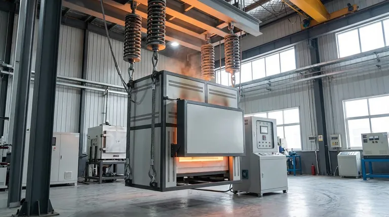
In mechanical constraint simulations, expansion compensation devices like spring suspension systems are modeled by explicitly permitting movement along a specific directional axis, typically the vertical (Z) axis. Rather than applying rigid displacement constraints that lock the equipment in place, the finite element model is defined to allow free translation in this direction to mimic physical reality.
By removing rigid constraints on the suspension axis, the model accurately simulates the equipment's "self-compensation" capability. This ensures that the calculated thermal stresses reflect the actual relief provided by the suspension system during operation.
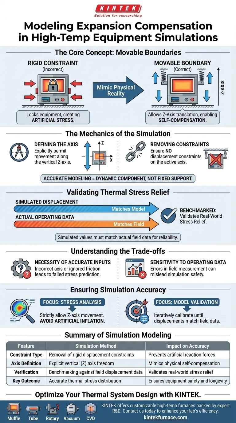
The Mechanics of the Simulation
Defining the Axis of Movement
To replicate the behavior of high-temperature equipment, the simulation must account for directional freedom.
In the finite element model, the boundary conditions for the spring suspension are set to allow movement specifically along the vertical Z-axis. This distinguishes the suspension points from fixed anchor points, which would otherwise restrict all motion.
Removing Displacement Constraints
The key to accurate modeling is the absence of artificial restrictions.
The simulation setup must ensuring that no displacement constraints are imposed on the suspension's active axis. This prevents the mathematical model from generating artificial reaction forces that would not exist in the real-world physical system.
Validating Thermal Stress Relief
Simulating Self-Compensation
High-temperature equipment expands naturally when heated.
By modeling the suspension as a movable boundary, the simulation captures the equipment's ability to self-compensate. This confirms that the equipment can expand without generating excessive internal stresses that would occur if it were rigidly constrained.
Benchmarking Against Real Data
The reliability of the simulation depends on verification.
Engineers assess the effectiveness of the model by comparing the simulated displacement values directly with actual operating data. If the simulation moves the same amount as the real equipment, the model is considered a valid predictor of thermal stress relief.
Understanding the Trade-offs
The Necessity of Accurate Inputs
While this modeling approach is realistic, it relies heavily on the quality of the boundary definitions.
If the axis of movement is defined incorrectly, or if friction is ignored where it shouldn't be, the model will fail to predict the true stress distribution.
Sensitivity to Operating Data
The validation process is only as good as the field data available.
Because the model is validated by matching actual operating data, any errors in field measurement can lead to a false sense of security regarding the safety of the simulation results.
Ensuring Simulation Accuracy
To effectively model expansion compensation in your projects:
- If your primary focus is Stress Analysis: Ensure your boundary conditions strictly allow movement along the vertical Z-axis to avoid artificially inflating stress values.
- If your primary focus is Model Validation: Calibrate your simulation by iteratively adjusting parameters until the simulated displacements match your recorded field data.
Accurate modeling requires treating the suspension not as a fixed support, but as a dynamic component that breathes with the equipment.
Summary Table:
| Feature | Simulation Method | Impact on Accuracy |
|---|---|---|
| Constraint Type | Removal of rigid displacement constraints | Prevents artificial reaction forces |
| Axis Definition | Explicit vertical (Z) axis freedom | Mimics physical self-compensation |
| Verification | Benchmarking against field displacement data | Validates real-world stress relief |
| Key Outcome | Accurate thermal stress distribution | Ensures equipment safety and longevity |
Optimize Your Thermal System Design with KINTEK
Ensure your high-temperature equipment is built for durability and performance. Backed by expert R&D and manufacturing, KINTEK offers a wide range of laboratory solutions including Muffle, Tube, Rotary, Vacuum, and CVD systems. Our high-temp furnaces are fully customizable to accommodate unique expansion compensation needs and complex mechanical constraints.
Ready to enhance your lab's thermal processing efficiency? Contact us today to discuss how our customizable systems can meet your exact research and production requirements.
Visual Guide
References
- Nenghong Zheng, Ye Chen. Numerical Simulation Research on Screen Superheater of Supercritical Circulating Fluidized Bed Boiler. DOI: 10.54691/czsm3b20
This article is also based on technical information from Kintek Furnace Knowledge Base .
Related Products
- 1700℃ High Temperature Muffle Oven Furnace for Laboratory
- 1800℃ High Temperature Muffle Oven Furnace for Laboratory
- 1400℃ Muffle Oven Furnace for Laboratory
- High Temperature Muffle Oven Furnace for Laboratory Debinding and Pre Sintering
- Laboratory Muffle Oven Furnace with Bottom Lifting
People Also Ask
- What is the importance of programmable temperature control in a muffle furnace? Master g-C3N4 Synthesis Precision
- How does the two-stage sintering process contribute to the synthesis of MeCuFeO3 perovskite? Optimize crystal purity.
- What role does a muffle furnace play in sintering photocathodes? Enhance Electrode Conductivity & Catalytic Activity
- What conditions does a muffle furnace provide for Fucus vesiculosus ash determination? Achieve Precise 700°C Ashing
- What functions does a high-temperature muffle furnace perform during cathode precursor processing?