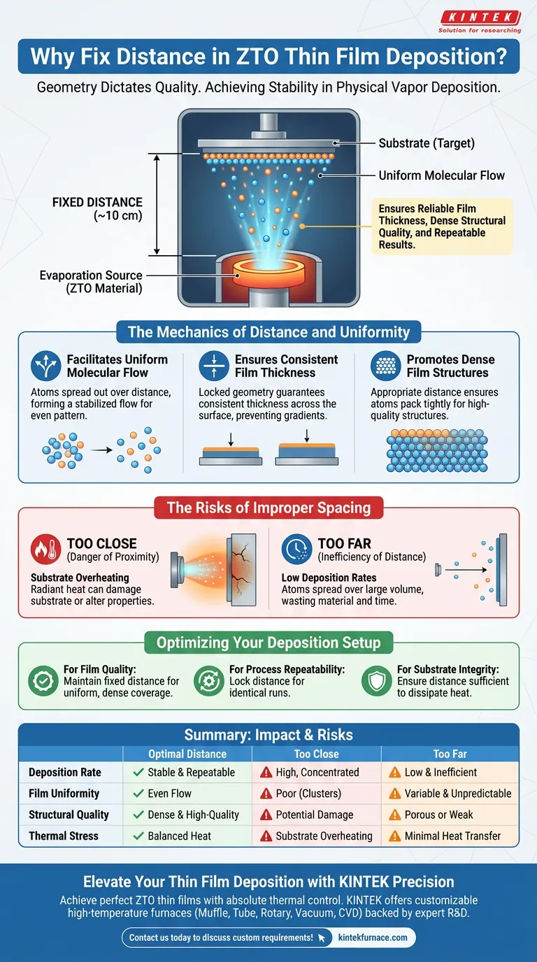
Maintaining a fixed source-to-substrate distance is the primary control for ensuring stability in ZTO thin film deposition. By keeping this distance constant, typically around 10 cm, you ensure that the evaporated atoms form a uniform molecular flow. This consistency is essential for achieving reliable film thickness, dense structural quality, and repeatable results across multiple fabrication runs.
The Core Insight In physical vapor deposition, geometry dictates quality. A fixed distance balances the thermodynamics of the process, allowing gas-phase atoms to distribute evenly without subjecting the substrate to excessive heat or suffering from inefficient deposition rates.
The Mechanics of Distance and Uniformity
Facilitating Uniform Molecular Flow
When atoms evaporate from the source, they initially move in a somewhat chaotic or concentrated manner.
Distance allows these gas-phase atoms to spread out. By the time they travel a fixed path (e.g., 10 cm), they form a stabilized molecular flow, ensuring they land on the substrate in a uniform pattern rather than a concentrated cluster.
Ensuring Consistent Film Thickness
Variation in distance leads to immediate variation in how much material lands on the substrate.
By fixing the distance, you lock in the deposition geometry. This guarantees that the thickness of the ZTO film remains consistent across the entire surface area of the substrate, preventing gradients that could ruin device performance.
Promoting Dense Film Structures
The energy and density of the atoms arriving at the substrate affect how they pack together.
An appropriate, fixed distance ensures the atoms arrive with the right trajectory and distribution to form dense, high-quality structures. Without this fixed parameter, films might become porous or structurally weak.
The Risks of Improper Spacing
The Danger of Proximity (Too Close)
Placing the substrate too close to the source creates a harsh thermal environment.
The primary risk here is substrate overheating. If the distance is too short, the radiant heat from the evaporation source can damage the substrate or alter the properties of the film being deposited.
The Inefficiency of Distance (Too Far)
Conversely, increasing the distance beyond the optimal point introduces inefficiency.
Excessive distance results in low deposition rates. As the plume of atoms spreads out over a larger volume, fewer atoms actually hit the target, wasting source material and significantly extending the time required to grow the film.
Optimizing Your Deposition Setup
To achieve high-quality ZTO thin films, you must view distance not as a variable, but as a fixed constant in your equation.
- If your primary focus is Film Quality: Maintain the standard fixed distance (e.g., 10 cm) to ensure the atoms have time to form a uniform flow for dense, even coverage.
- If your primary focus is Process Repeatability: Lock the distance mechanically to ensure that every run produces identical thickness and structural characteristics.
- If your primary focus is Substrate Integrity: Ensure the distance is sufficient to dissipate radiant heat, preventing thermal damage to delicate substrates.
Precision in your physical setup is the only path to precision in your material performance.
Summary Table:
| Parameter | Impact of Optimal Distance | Risk of Being Too Close | Risk of Being Too Far |
|---|---|---|---|
| Deposition Rate | Stable and repeatable | High, but concentrated | Low and inefficient |
| Film Uniformity | Even molecular flow | Poor (concentrated clusters) | Variable and unpredictable |
| Structural Quality | Dense and high-quality | Potential thermal damage | Porous or weak structure |
| Thermal Stress | Balanced heat distribution | Substrate overheating | Minimal heat transfer |
Elevate Your Thin Film Deposition with KINTEK Precision
Achieving the perfect ZTO thin film requires more than just the right materials—it requires absolute control over your thermal environment. Backed by expert R&D and world-class manufacturing, KINTEK offers a comprehensive range of lab high-temperature furnaces, including Muffle, Tube, Rotary, Vacuum, and CVD systems, all fully customizable to meet your unique research needs.
Don't let inconsistent geometry compromise your material performance. Our specialized systems are designed to provide the stability and repeatability your laboratory demands. Contact us today to discuss your custom deposition requirements with our technical experts!
Visual Guide
References
- Ashish Khandelwal, K. S. Sharma. Effect of Different Compositions of Mixed Metal Oxides (Zinc Oxide and Tin Oxide) on Structural and Optical Properties for the Application of Window Layers in Solar Cells. DOI: 10.3329/jsr.v16i1.64157
This article is also based on technical information from Kintek Furnace Knowledge Base .
Related Products
- RF PECVD System Radio Frequency Plasma Enhanced Chemical Vapor Deposition
- MPCVD Machine System Reactor Bell-jar Resonator for Lab and Diamond Growth
- 915MHz MPCVD Diamond Machine Microwave Plasma Chemical Vapor Deposition System Reactor
- HFCVD Machine System Equipment for Drawing Die Nano Diamond Coating
- Custom Made Versatile CVD Tube Furnace Chemical Vapor Deposition CVD Equipment Machine
People Also Ask
- What are the system specifications of the PECVD system? Unlock Precision Thin-Film Deposition
- What is RF in PECVD? A Critical Control for Plasma Deposition
- What is the role of RF power in PECVD and how does the RF-PECVD process work? Master Thin Film Deposition Control
- What are the key advantages of PECVD technology? Achieve Low-Temperature, High-Quality Thin Film Deposition
- How are deposition rates and film properties controlled in PECVD? Master Key Parameters for Optimal Thin Films