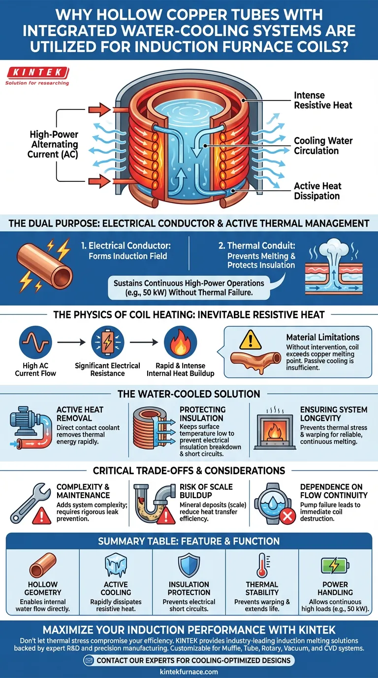
Hollow copper tubes serve a dual purpose in induction furnaces: they act as the electrical conductor for the induction field and a conduit for active thermal management. Because induction melting requires high-power currents, the coil itself generates significant resistive heat that would otherwise destroy the equipment. The hollow design facilitates the circulation of cooling water directly through the conductor, preventing the copper from melting and ensuring the integrity of the electrical insulation.
By integrating water cooling into the conductor design, induction coils can sustain continuous high-power operations (such as 50 kW) without thermal failure. This mechanism effectively dissipates resistive heat losses to preserve both the structural and electrical integrity of the furnace.
The Physics of Coil Heating
The Inevitability of Resistive Heat
Induction furnaces operate by passing massive alternating currents through a coil. While the primary goal is to heat the metal inside the furnace, the coil itself is not a perfect superconductor.
Internal Heat Generation
As current flows through the copper, electrical resistance generates a significant amount of "waste" heat within the coil. At high power levels, such as 50 kW, this internal heat buildup is rapid and intense.
Material Limitations
Without active intervention, the temperature of the coil would quickly rise above the melting point of copper. Passive air cooling is insufficient to handle thermal loads of this magnitude.
The Water-Cooled Solution
Active Heat Removal
The hollow geometry allows water to flow through the center of the conductor, placing the coolant in direct contact with the heat source. This ensures the continuous removal of thermal energy as fast as it is generated.
Protecting Electrical Insulation
The copper is not the only vulnerable component; the electrical insulation between the coil turns is highly sensitive to heat. Water cooling keeps the surface temperature of the coil low enough to prevent insulation breakdown and short circuits.
Ensuring System Longevity
By stabilizing the temperature, the water-cooling system prevents thermal stress and warping. This allows the furnace to run reliable, continuous melting cycles without degrading the hardware.
Critical Trade-offs and Considerations
Complexity and Maintenance
Introducing water into an electrical system adds complexity. Operators must rigorously maintain the cooling loop to prevent leaks, which could cause catastrophic electrical faults.
The Risk of Scale Buildup
Over time, mineral deposits or "scale" can build up inside the hollow tubes. This acts as an insulator, reducing heat transfer efficiency and potentially leading to localized overheating.
Dependence on Flow Continuity
The system becomes entirely dependent on the water pump. A failure in water flow, even for a brief period during operation, can lead to immediate coil destruction.
Maximizing Coil Reliability
To ensure the safety and efficiency of your induction system, consider the following operational priorities:
- If your primary focus is continuous high-power operation: Ensure your cooling system is rated to dissipate the specific heat load generated at peak power (e.g., 50 kW).
- If your primary focus is system longevity: Implement strict water quality controls and filtration to prevent mineral buildup inside the hollow copper tubes.
- If your primary focus is safety: Install redundant flow sensors that automatically shut down the power supply if water pressure drops.
The integration of hollow, water-cooled tubes turns the limiting factor of resistive heat into a manageable operational variable.
Summary Table:
| Feature | Function & Benefit |
|---|---|
| Hollow Geometry | Enables internal water flow directly through the electrical conductor. |
| Active Cooling | Rapidly dissipates resistive heat to prevent the copper from melting. |
| Insulation Protection | Maintains low surface temperatures to prevent electrical short circuits. |
| Thermal Stability | Prevents structural warping and extends the operational life of the coil. |
| Power Handling | Allows continuous operation at high loads (e.g., 50 kW) without failure. |
Maximize Your Induction Performance with KINTEK
Don't let thermal stress compromise your laboratory's efficiency. KINTEK provides industry-leading induction melting solutions backed by expert R&D and precision manufacturing. Whether you require Muffle, Tube, Rotary, Vacuum, or CVD systems, our high-temp furnaces are fully customizable to meet your specific thermal management needs.
Ensure system longevity and operational safety with equipment designed for the most demanding high-power applications. Contact our technical experts today to discover how our cooling-optimized designs can enhance your research and production outcomes.
Visual Guide
References
- Pablo Garcia-Michelena, Xabier Chamorro. Numerical Simulation of Free Surface Deformation and Melt Stirring in Induction Melting Using ALE and Level Set Methods. DOI: 10.3390/ma18010199
This article is also based on technical information from Kintek Furnace Knowledge Base .
Related Products
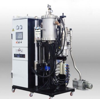
- Vacuum Induction Melting Furnace
- 600T Vacuum Induction Hot Press Vacuum Heat Treat and Sintering Furnace
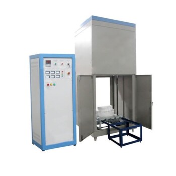
- 1200℃ Controlled Inert Nitrogen Atmosphere Furnace
- 1700℃ Controlled Inert Nitrogen Atmosphere Furnace
- Mesh Belt Controlled Atmosphere Furnace Inert Nitrogen Atmosphere Furnace
People Also Ask
- Why is a Vacuum Induction Melting furnace (VIM) used for Cu-Zn-Al-Sn alloys? Achieve Precision Composition Control
- What are the advantages of using a VIM furnace to control residual oxygen pressure? Achieve Superior Metal Uniformity
- What is the core function of a Vacuum Induction Melting (VIM) furnace? Master High-Manganese Steel Preparation
- What role does a Vacuum Induction Melting furnace play in the production of high-aluminum nickel-based superalloys?
- What are the technical advantages of using a Vacuum Induction Melting furnace in the development of advanced packaging steel?