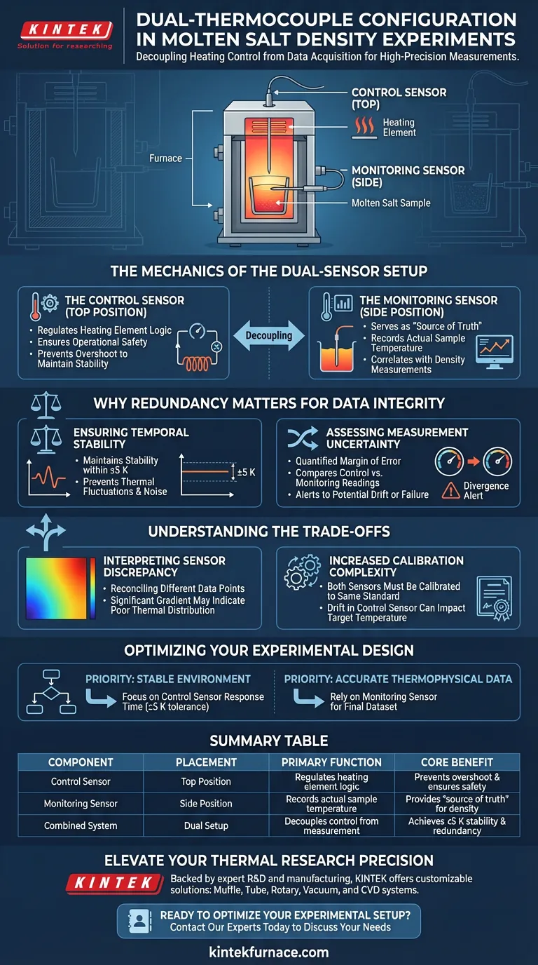
In high-precision molten salt density experiments, a dual-thermocouple configuration is essential for decoupling the heating control loop from the actual data acquisition. Specifically, one thermocouple is placed at the top of the apparatus to regulate the heating element, while a second thermocouple is positioned on the side to monitor the actual temperature of the molten sample.
By separating the control sensor from the measurement sensor, this setup ensures thermal stability within ±5 K and provides the necessary redundancy to calculate measurement uncertainty.
The Mechanics of the Dual-Sensor Setup
The Control Sensor (Top Position)
The primary function of the top-positioned thermocouple is operational safety and regulation.
It connects directly to the heating element's control logic.
Its goal is to drive the system to the setpoint without causing overshoot that could destabilize the experiment.
The Monitoring Sensor (Side Position)
The side-positioned thermocouple serves as the "source of truth" for the experiment.
It is placed closer to the sample assembly to record the actual temperature the molten salt is experiencing.
This is the data point used for correlating density measurements with specific temperatures.
Why Redundancy Matters for Data Integrity
Ensuring Temporal Stability
Molten salts require precise thermal environments to yield accurate physical property data.
The dual configuration allows the system to maintain a temperature stability of ±5 K.
This prevents thermal fluctuations from introducing noise into the density readings over time.
Assessing Measurement Uncertainty
Reliable data requires a quantified margin of error.
By comparing the readings from the control sensor (top) and the monitor sensor (side), researchers can assess measurement uncertainty.
If the divergence between the two sensors exceeds expected parameters, it alerts the operator to potential equipment drift or failure.
Understanding the Trade-offs
Interpreting Sensor Discrepancy
While redundancy improves confidence, it introduces the challenge of reconciling two different data points.
A significant temperature gradient between the top and side sensors may indicate poor thermal distribution within the furnace, rather than sensor error.
Increased Calibration Complexity
Using two sensors requires that both be calibrated to the same standard.
If the control thermocouple drifts but the monitoring thermocouple remains accurate, the system may struggle to reach the target temperature despite accurate reporting.
Optimizing Your Experimental Design
To maximize the effectiveness of a dual-thermocouple setup, align your sensor usage with your specific data requirements:
- If your primary focus is maintaining a stable environment: Prioritize the response time of the top thermocouple to ensure the heating element stays within the ±5 K tolerance.
- If your primary focus is reporting accurate thermophysical data: Rely exclusively on the side thermocouple for your final dataset, using the top sensor only for background regulation.
rigorous thermal management is the baseline requirement for producing reliable thermophysical property data.
Summary Table:
| Component | Placement | Primary Function | Core Benefit |
|---|---|---|---|
| Control Sensor | Top Position | Regulates heating element logic | Prevents overshoot & ensures safety |
| Monitoring Sensor | Side Position | Records actual sample temperature | Provides 'source of truth' for density |
| Combined System | Dual Setup | Decouples control from measurement | Achieves ±5 K stability & redundancy |
Elevate Your Thermal Research Precision
Reliable thermophysical data starts with rigorous thermal management. Backed by expert R&D and manufacturing, KINTEK offers a wide range of customizable solutions, including Muffle, Tube, Rotary, Vacuum, and CVD systems. Whether you are conducting molten salt experiments or advanced material synthesis, our lab high-temperature furnaces provide the stability and control your research demands.
Ready to optimize your experimental setup? Contact our experts today to discuss your unique needs
Visual Guide
References
- Jisue Moon, Theodore M. Besmann. Density Measurements of Molten LiF–BeF<sub>2</sub> and LiF–BeF<sub>2</sub>–LaF<sub>3</sub> Salt Mixtures by Neutron Radiography. DOI: 10.1021/acsomega.4c01446
This article is also based on technical information from Kintek Furnace Knowledge Base .
Related Products
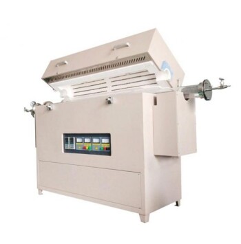
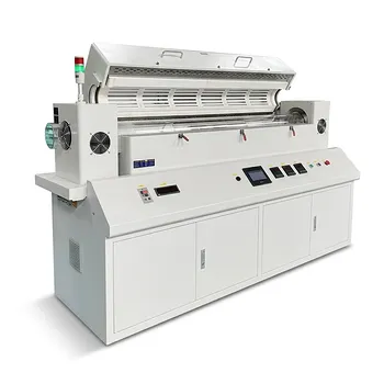
- Multi Heating Zones CVD Tube Furnace Machine for Chemical Vapor Deposition Equipment
- Multi Zone Laboratory Quartz Tube Furnace Tubular Furnace
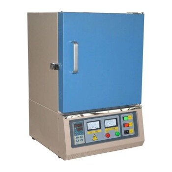
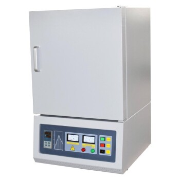
- High Temperature Muffle Oven Furnace for Laboratory Debinding and Pre Sintering
- Split Multi Heating Zone Rotary Tube Furnace Rotating Tube Furnace
- Vertical Laboratory Quartz Tube Furnace Tubular Furnace
People Also Ask
- What are the advantages of multi-zone tube furnaces? Achieve Superior Thermal Control for Advanced Materials Processing
- What role does a Tube Furnace play in the CVD growth of carbon nanotubes? Achieve High-Purity CNT Synthesis
- What role do multi zone tube furnaces play in new energy research? Unlock Precise Thermal Control for Innovation
- What temperature-related capabilities make multi zone tube furnaces valuable for research? Unlock Precision Thermal Control
- What are the main applications of multi zone tube furnaces in university laboratories? Unlock Precision in Material Science and Energy Research