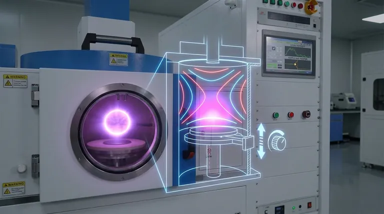
In a Microwave Plasma Chemical Vapor Deposition (MPCVD) system, the position of the sample base is a fundamental control parameter, not a passive component. Adjusting its vertical position directly alters the geometry of the plasma chamber. This change has a profound and immediate effect on the electric field, which in turn governs the intensity, shape, and location of the plasma used for material deposition.
Think of the MPCVD chamber not just as a container, but as a finely-tuned microwave resonator. The sample base acts as a tuning piston. Adjusting its position changes the resonant properties of the entire cavity, directly shaping the plasma that drives your deposition process.
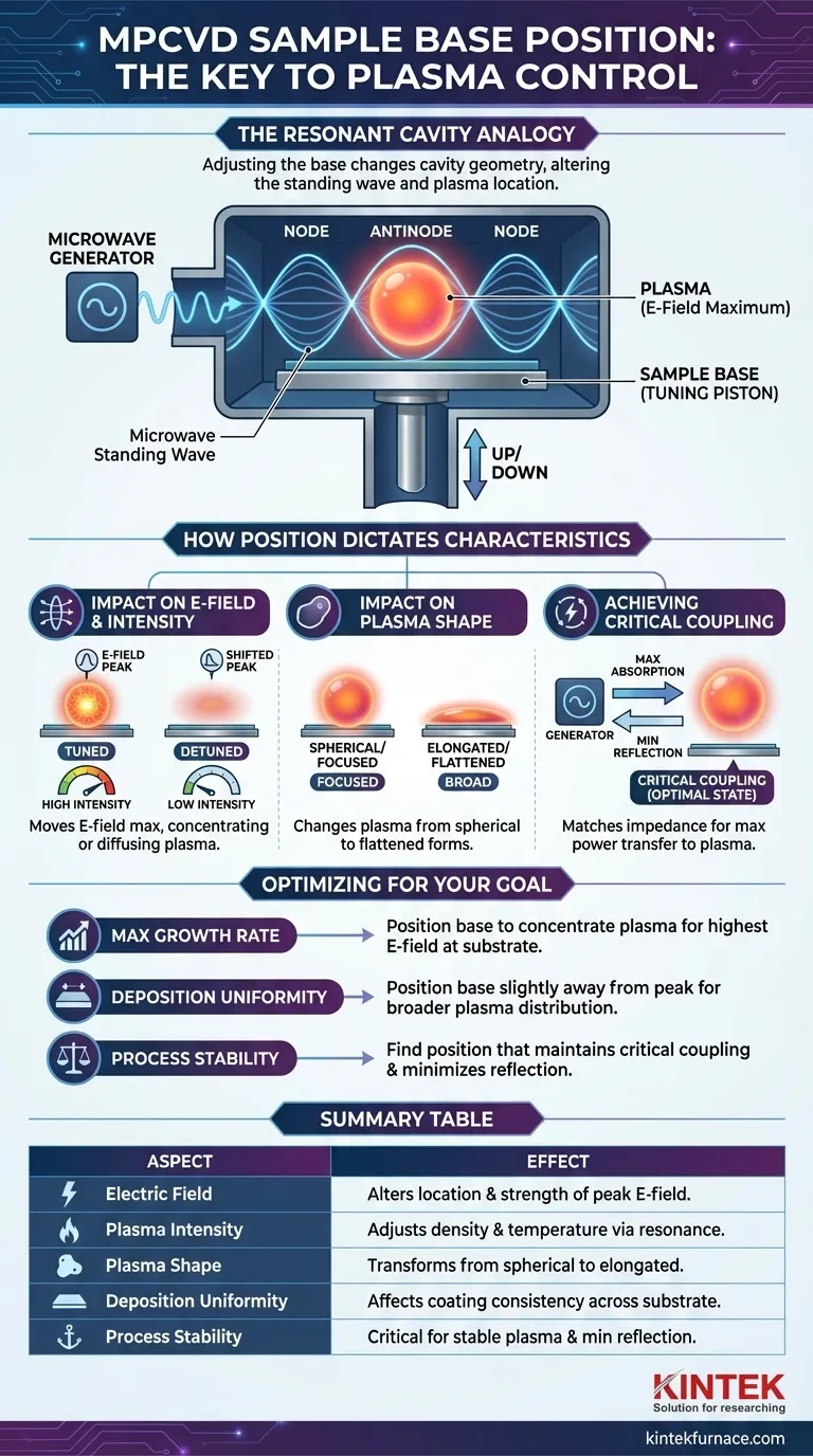
The MPCVD Chamber as a Resonant Cavity
To understand the role of sample position, you must first understand that an MPCVD chamber is engineered to function as a resonant cavity, similar to the body of a musical instrument.
How Microwaves Generate Plasma
The system's microwave generator injects electromagnetic energy (typically at 2.45 GHz) into the sealed chamber. This energy forms a standing wave pattern with distinct areas of high and low energy.
Plasma is initiated and sustained at the antinode, which is the point of the maximum electric field (E-field) strength. At this location, the intense E-field accelerates free electrons, causing them to collide with and ionize gas atoms, creating a self-sustaining plasma ball.
The Sample Base as a Tuning Element
The conductive sample base, or substrate holder, acts as one of the physical boundaries of this resonant cavity. When you move the sample base up or down, you are changing the dimensions of the cavity.
This change in geometry alters the standing wave pattern inside the chamber. It effectively moves the location of the E-field maximum, changing where the plasma forms and how intense it becomes.
How Sample Position Dictates Plasma Characteristics
By tuning the cavity geometry, you gain direct control over the plasma's most critical properties. The position of the base is the mechanism you use to translate microwave power into a useful deposition environment.
Impact on the Electric Field
Moving the sample base changes the location of the peak electric field. The goal is often to position the substrate directly within this high-energy zone to maximize the efficiency of the deposition process.
A properly positioned base ensures the cavity is "tuned" for maximum power absorption from the microwaves.
Impact on Plasma Intensity and Shape
The intensity and shape of the plasma are direct consequences of the E-field distribution. Where the E-field is strongest and most focused, the plasma will be densest and hottest.
Adjusting the sample position can change a spherical plasma ball into an elongated or flattened shape. It can also be used to center the plasma perfectly over the substrate or intentionally offset it if needed.
Achieving Critical Coupling
The ultimate operational goal is to achieve critical coupling. This is the state where the impedance of the plasma matches the impedance of the microwave source.
At critical coupling, nearly all the microwave power is absorbed by the plasma and used for deposition, with minimal power reflected back to the generator. The sample base position is a primary tool for achieving this optimal state.
Understanding the Trade-offs and Pitfalls
While powerful, adjusting the sample position is a balancing act with significant consequences if done incorrectly.
The Search for the "Sweet Spot"
The optimal position is a compromise. The position that yields the highest plasma intensity might not produce the most uniform coating across a large substrate. You must find the balance that meets your specific process requirements for rate, quality, and uniformity.
The Risk of Instability or Extinction
Moving the base too far from the optimal position will "detune" the cavity. This causes a severe impedance mismatch, leading to a large amount of reflected power.
The result can be an unstable, flickering plasma or a complete plasma extinction, as insufficient energy is being coupled to the gas.
Interdependence with Other Parameters
The ideal sample position is not a fixed constant. It is highly dependent on other process parameters, such as microwave power, gas pressure, and gas composition. A change in any of these variables will often require a corresponding adjustment of the sample base to re-optimize the plasma coupling.
Optimizing Sample Position for Your Goal
The ideal sample position depends entirely on your experimental objective. Use the following as a guide for your tuning process.
- If your primary focus is maximum growth rate: You should position the base to concentrate the plasma, creating the highest possible E-field intensity directly at the substrate surface.
- If your primary focus is deposition uniformity: You may need to position the base slightly away from the point of maximum intensity to create a broader, more evenly distributed plasma across your substrate.
- If your primary focus is process stability: Your goal is to find a position that maintains critical coupling, minimizing reflected power and ensuring a stable plasma shape even with minor fluctuations in other parameters.
Mastering the position of your sample base transforms it from a simple holder into your most powerful tool for process control.
Summary Table:
| Aspect | Effect of Sample Base Position |
|---|---|
| Electric Field | Alters location and strength of peak E-field, influencing plasma formation |
| Plasma Intensity | Adjusts plasma density and temperature by changing cavity resonance |
| Plasma Shape | Can transform plasma from spherical to elongated or flattened forms |
| Deposition Uniformity | Affects coating consistency across the substrate surface |
| Process Stability | Critical for achieving stable plasma and minimizing power reflection |
Unlock Precision in Your MPCVD Processes with KINTEK! Leveraging exceptional R&D and in-house manufacturing, we provide diverse laboratories with advanced high-temperature furnace solutions, including CVD/PECVD Systems. Our strong deep customization capability ensures we precisely meet your unique experimental requirements for plasma control and material deposition. Contact us today to discuss how our tailored solutions can enhance your research and production efficiency!
Visual Guide
Related Products
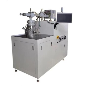
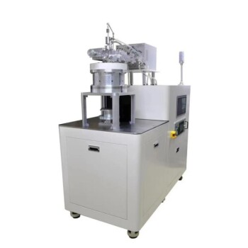
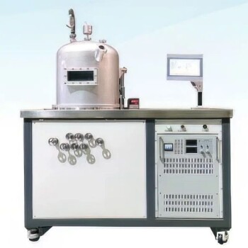
- Cylindrical Resonator MPCVD Machine System for Lab Diamond Growth
- MPCVD Machine System Reactor Bell-jar Resonator for Lab and Diamond Growth
- 915MHz MPCVD Diamond Machine Microwave Plasma Chemical Vapor Deposition System Reactor
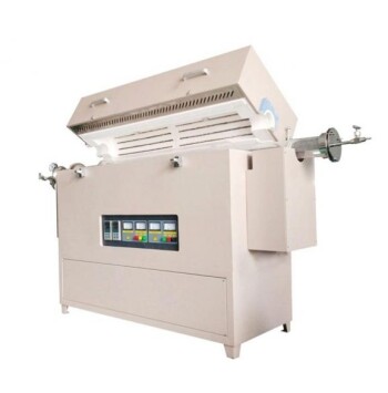
- Multi Heating Zones CVD Tube Furnace Machine for Chemical Vapor Deposition Equipment
- Slide PECVD Tube Furnace with Liquid Gasifier PECVD Machine
People Also Ask
- What factors influence the quality of diamond deposition in the MPCVD method? Master the Critical Parameters for High-Quality Diamond Growth
- Why is temperature control important in the MPCVD growth process? Ensure High-Quality, Reliable Diamond Film Deposition
- How does pressure affect the MPCVD growth process? Master Plasma Control for Superior Film Quality
- What are the essential components of an MPCVD reactor system? Build a Pristine Environment for High-Purity Materials
- How does MPCVD achieve stable temperature control during diamond growth? Master Precise Thermal Management