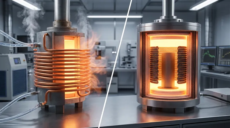
Macroscopic graphene materials fundamentally alter the efficiency of induction furnaces by removing the thermal limitations inherent to traditional copper. The primary advantage is the ability to place the induction coil inside the insulation layer, significantly closer to the heating element, which dramatically improves electromagnetic coupling and eliminates the need for energy-wasting water cooling systems.
By replacing actively cooled copper with high-temperature resistant graphene, you effectively turn the induction coil from a heat sink into a heat source. This shift not only captures resistive energy that is usually lost but also allows for a tighter, more efficient electromagnetic coupling with the furnace load.
Redefining Thermal Management
Elimination of Active Cooling Systems
Traditional copper coils have a relatively low thermal tolerance, necessitating complex internal water cooling systems to prevent melting during high-temperature operation.
Graphene materials possess exceptional high-temperature resistance, allowing them to operate safely without liquid cooling.
This simplifies the overall furnace design by removing pumps, plumbing, and the risk of water leaks within the high-heat zone.
Converting Resistive Loss to Thermal Gain
In a copper setup, the heat generated by the coil’s electrical resistance is a waste product that must be carried away by the cooling water.
With graphene coils, this resistive heat is retained within the thermal insulation.
Instead of being extracted and wasted, the heat generated by the coil contributes to the overall thermal energy of the furnace, directly improving thermal performance.
Maximizing Electromagnetic Efficiency
Strategic Coil Positioning
Because copper coils require cooling and protection from extreme heat, they must be positioned outside the furnace's insulation layer.
The high thermal resistance of graphene allows the coil to be moved inside the insulation layer, inhabiting the same high-temperature environment as the workload.
Enhanced Coupling Efficiency
Moving the coil inside the insulation places it in closer proximity to the graphite heating element.
This reduced physical distance significantly enhances the electromagnetic coupling efficiency between the coil and the load.
The result is a more direct transfer of energy with fewer losses across the gap between the inductor and the susceptor.
Understanding the Design Implications
The Shift from Component to System
Adopting graphene coils is not a simple "drop-in" replacement for copper; it represents a fundamental change in furnace architecture.
Managing Internal Heat Loads
Because the coil no longer removes heat via water, the furnace design must account for the additional thermal load retained inside the insulation.
Engineers must ensure the insulation stack is designed to manage this retained heat effectively, rather than relying on the coil to act as a partial heat sink.
Making the Right Choice for Your Goal
To determine if macroscopic graphene coils are the right solution for your high-temperature furnace, consider your primary engineering constraints:
- If your primary focus is energy efficiency: Leverage graphene to utilize resistive heat loss as productive energy and maximize electromagnetic coupling through closer proximity.
- If your primary focus is system simplicity: Use graphene to eliminate the maintenance liability, complexity, and failure points associated with water cooling subsystems.
By integrating the coil into the hot zone, you bridge the gap between energy generation and application, creating a more unified and efficient thermal system.
Summary Table:
| Feature | Traditional Copper Coils | Macroscopic Graphene Coils |
|---|---|---|
| Cooling Requirement | Active water-cooling (high maintenance) | No liquid cooling needed |
| Placement | Outside insulation layer (distant) | Inside insulation layer (close) |
| Resistive Heat | Wasted as heat sink loss | Retained as productive thermal gain |
| Coupling Efficiency | Lower due to physical distance | Higher due to proximity to load |
| System Complexity | High (pumps, plumbing, leak risks) | Low (simplified furnace architecture) |
Upgrade to Next-Generation Thermal Performance with KINTEK
Is your high-temperature process hindered by the limitations of traditional water-cooled copper coils? At KINTEK, we bridge the gap between innovation and application. Backed by expert R&D and world-class manufacturing, we offer Muffle, Tube, Rotary, Vacuum, and CVD systems, alongside specialized high-temp furnaces that can be customized for your unique graphene or graphite integration needs.
By choosing KINTEK, you gain access to a partner dedicated to maximizing your energy efficiency and system reliability. Whether you are looking to eliminate complex cooling subsystems or redefine your thermal architecture, our team is ready to deliver the solution.
Ready to optimize your lab's heating efficiency? Contact us today to discuss your custom furnace requirements!
References
- Rui Li, Hongda Du. Design and Numerical Study of Induction-Heating Graphitization Furnace Based on Graphene Coils. DOI: 10.3390/app14062528
This article is also based on technical information from Kintek Furnace Knowledge Base .
Related Products
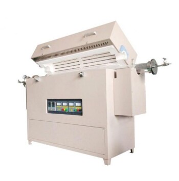
- Multi Heating Zones CVD Tube Furnace Machine for Chemical Vapor Deposition Equipment
- 1200℃ Controlled Inert Nitrogen Atmosphere Furnace
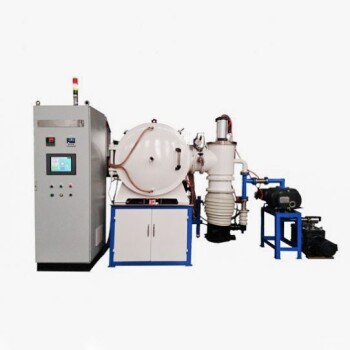
- Vacuum Induction Melting Furnace
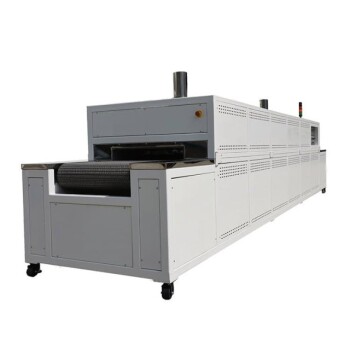
- High Temperature Muffle Oven Furnace for Laboratory Debinding and Pre Sintering
- 600T Vacuum Induction Hot Press Vacuum Heat Treat and Sintering Furnace
People Also Ask
- What are the benefits of integrating multiple heating zones in a tube furnace? Unlock Precise Thermal Control
- Why are multi zone tube furnaces particularly useful for nanomaterial research? Unlock Precise Thermal Control for Advanced Synthesis
- What is the function of a multi-zone tube furnace in CVD synthesis? Master 2D In2Se3 Nanosheet Precision
- What environmental protection applications utilize multi zone tube furnaces? Unlock Precision in Waste Treatment and Green Tech
- How are multi zone tube furnaces used in ceramics, metallurgy and glass research? Unlock Precise Thermal Control for Advanced Materials