Simple analytical models of neck growth and diffusion during sintering—like the classic two-particle equations—fail to capture the true physics because they rely on a flawed geometrical simplification. The “circle approximation” assumes the neck surface is a circular arc that meets the particle tangentially, creating an unphysical jump in curvature and chemical potential that doesn’t exist in a real powder compact heated in your high‑temperature furnace. Real necks evolve with continuous curvature variation, surface undercutting, and simultaneous activity of multiple diffusion mechanisms, all of which simple models ignore.
While these models give a valuable starting point for thinking about kinetics, their predictive power is fundamentally limited by an oversimplified neck geometry, the assumption of a single dominant transport mechanism, and the neglect of concurrent microstructural changes like grain growth and surface diffusion. As a result, real shrinkage and neck evolution in your furnace often diverge dramatically from analytical predictions, making empirical microstructural validation indispensable.
The Core Geometrical Flaw: The Circle Approximation
An Artificial Discontinuity That Distorts the Driving Force
The classic two‑sphere sintering model describes the neck as a circular arc that tangentially joins the particle surface. At the point of tangency, the curvature jumps from a finite value (on the particle) to a different value (on the neck arc).
This discontinuity creates a fictitious spike in chemical potential, which is the fundamental driver for vacancy and atom migration. In a real furnace, such a sharp transition does not exist; the neck surface transitions smoothly with a continuously varying curvature.
Missing Undercutting and Continuous Curvature Evolution
High‑resolution numerical simulations and experimental observations show that real necks develop a gently curved profile with a minimum radius of curvature near the center—often accompanied by subtle undercutting just below the original particle surface.
The circle approximation cannot reproduce this undercutting or the continuous reduction in curvature that dictates the true diffusion gradient. Consequently, simple models miscalculate the chemical potential distribution that drives mass transport into the neck.
The Fallacy of a Single Dominant Diffusional Mechanism
Ignoring Concurrent Transport Pathways
Simple models assign a single kinetic exponent m (e.g., m=6 for grain boundary diffusion) and assume one mechanism controls the entire process. In reality, surface diffusion, grain boundary diffusion, and volume diffusion often operate concurrently, especially during the ramp segments of a furnace cycle.
The primary limitation here is cross‑talk between mechanisms: surface diffusion can rapidly smooth and widen the neck without shrinkage, while grain boundary diffusion simultaneously draws material from the boundary region. A single‑mechanism equation cannot capture this coupled behavior.
The Misleading Exponent Analysis
When researchers plot log(X‑/a) vs. log(t) and extract a slope 1/m, they assume one exponent represents the dominant mechanism. However, if multiple mechanisms are active, the measured exponent is an apparent composite value that doesn’t correspond to any single diffusional pathway.
As a result, relying on exponent analysis in simple models often leads to incorrect identification of the rate‑controlling process, especially in powder systems where surface diffusion can predominate during slow heating.
Unrealistic Assumptions About the Powder Compact
Idealized Monosize Spheres and Uniform Contacts
Analytical two‑sphere models begin with equal‑sized, perfectly spherical particles arranged in a uniform coordination geometry. Real powder compacts in your lab furnace consist of polydisperse, irregularly shaped particles with a distribution of contact angles and curvatures.
This deviation changes local diffusion distances and the initial curvature at every particle contact, making the simple r‑≈‑x²/(4a) relationship a gross oversimplification.
Isothermal, Homogeneous, and Time‑Invariant Conditions
Simple models assume constant temperature, uniform green density, and a static microstructure throughout the initial sintering stage. In practice, your furnace may have thermal gradients, and green density variations across a compact alter local sintering rates.
Even small batch‑to‑batch variations in powder characteristics or forming processes invalidate the strict assumptions required for predictive models like the Master Sintering Curve, highlighting the gap between analytical ideality and furnace reality.
Neglecting Microstructural Evolution That Competes With Neck Growth
Grain Growth and Non‑Densifying Coarsening
Simple neck‑growth equations treat grain size as constant or purely density‑dependent. In actual high‑temperature sintering, grain growth occurs simultaneously with neck evolution, changing both the density of diffusional paths and the local curvature of free surfaces.
More critically, surface diffusion is a non‑densifying mechanism that can dominate at lower temperatures and during slow ramps. It grows the neck area and coarsens pores by redistributing material along surfaces without bringing particle centers closer together, consuming the sintering driving force without contributing to shrinkage. Simple models that track only densifying fluxes miss this critical loss.
The Disconnect Between Neck Growth and Measurable Shrinkage
Because simple models often separate “with shrinkage” and “without shrinkage” versions into distinct cases, they fail to describe the continuous transition that occurs in a real furnace where surface diffusion and grain boundary diffusion occur side‑by‑side.
Your observed dimensional change in a tube or muffle furnace therefore deviates from any single analytical prediction, requiring you to interpret neck growth and shrinkage data together rather than in isolation.
Understanding the Trade‑offs
Despite their limitations, simple analytical models remain useful as a conceptual baseline and for fitting initial‑stage kinetics when mechanisms are well separated. The trade‑off is clear:
- Advantage: They offer closed‑form equations and physical intuition about how particle size, temperature, and time influence neck size.
- Limitation: They cannot predict real furnace behavior under typical processing conditions without extensive empirical calibration and careful control of heating profiles, atmospheres, and powder consistency.
The critical insight is that deviations between model and experiment are not noise—they reveal the influence of concurrent mechanisms and morphological complexity that you must address through furnace parameter adjustment and post‑sintering microstructural analysis.
Making the Right Choice for Your Sintering Analysis
How you apply this knowledge depends on your specific goal in the lab or pilot line.
- If your primary focus is establishing baseline kinetic trends: Use the simple two‑sphere equations to bound the problem, but treat the derived exponent as a semi‑quantitative indicator. Always validate neck morphologies with scanning electron microscopy.
- If your primary focus is predicting densification in a production furnace: Combine analytical equations with Master Sintering Curve concepts, but enforce strict consistency in green compact preparation and adjust heating rates to suppress surface diffusion. Recognize that a single apparent activation energy may mask multiple mechanisms.
- If your primary focus is understanding detailed neck evolution and mechanism interplay: Move beyond analytical models to numerical simulations that capture continuous curvature and concurrent diffusion. Run interrupted sintering experiments in your high‑temperature furnace to ground‑truth the simulated neck profiles and chemical potential distributions.
The best furnace recipe is never derived from idealized math alone—it comes from blending analytical insight with deliberate, observation‑driven furnace control.
Summary Table:
| Analytical Model Assumption | Real Sintering Reality | Impact on Kinetic Predictions |
|---|---|---|
| Circle Approximation | Continuous curvature evolution & surface undercutting | Distorts chemical potential and vacancy driving forces |
| Single Dominant Mechanism | Concurrent surface, grain boundary & volume diffusion | Yields misleading composite kinetic exponents (m) |
| Idealized Monosize Spheres | Polydisperse, irregular particles & non-uniform density | Alters local diffusion paths and initial contact geometry |
| Static Microstructure | Simultaneous grain growth & non-densifying surface diffusion | Causes major divergence between neck growth and shrinkage |
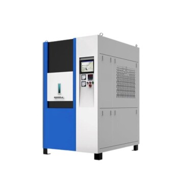
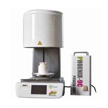
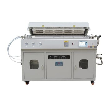
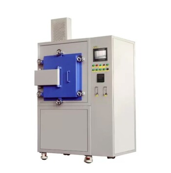
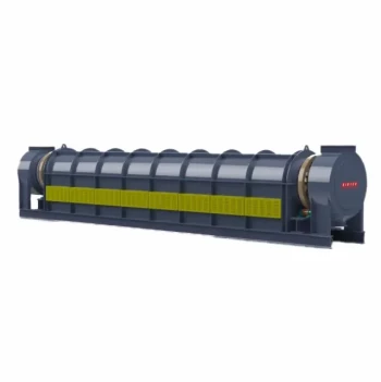
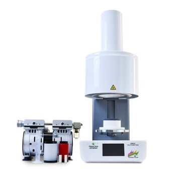
Bridge the gap between sintering theory and empirical success with KINTEK. High-precision material research demands reliable, tightly controlled thermal environments to accurately account for complex, concurrent diffusion mechanisms. KINTEK specializes in high-performance laboratory equipment and consumables, providing a comprehensive selection of high-temperature furnaces—including muffle, tube, rotary, vacuum, CVD, atmosphere, dental, and induction melting furnaces—all customizable to your specific research and production parameters.
Ready to achieve consistent microstructural validation and optimize your sintering profiles? Contact KINTEK today for custom furnace solutions!
Related Products
- Spark Plasma Sintering SPS Furnace
- Small Vacuum Heat Treat and Tungsten Wire Sintering Furnace
- High Temperature Muffle Oven Furnace for Laboratory Debinding and Pre Sintering
- Chairside Dental Porcelain Zirconia Sintering Furnace with Transformer for Ceramic Restorations
- Multi Heating Zones CVD Tube Furnace Machine for Chemical Vapor Deposition Equipment
People Also Ask
- How does the heating mechanism of Spark Plasma Sintering (SPS) function? Enhance TiC/SiC Composite Fabrication
- Why is it necessary to maintain a high vacuum environment during the SPS of SiC? Key to High-Density Ceramics
- What are the technical advantages of using an SPS sintering furnace? Elevate Al2O3-TiC Material Performance
- What are the steps in the discharge plasma sintering process? Master Fast, High-Density Material Consolidation
- What are the advantages of spark plasma sintering (SPS) over traditional forging? Precision Microstructural Control