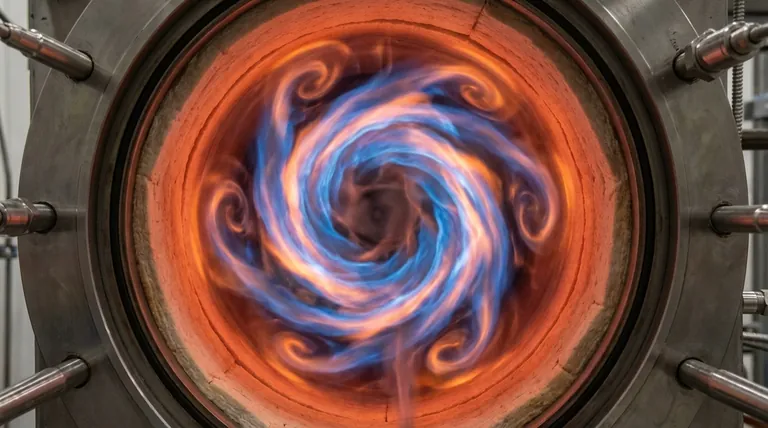
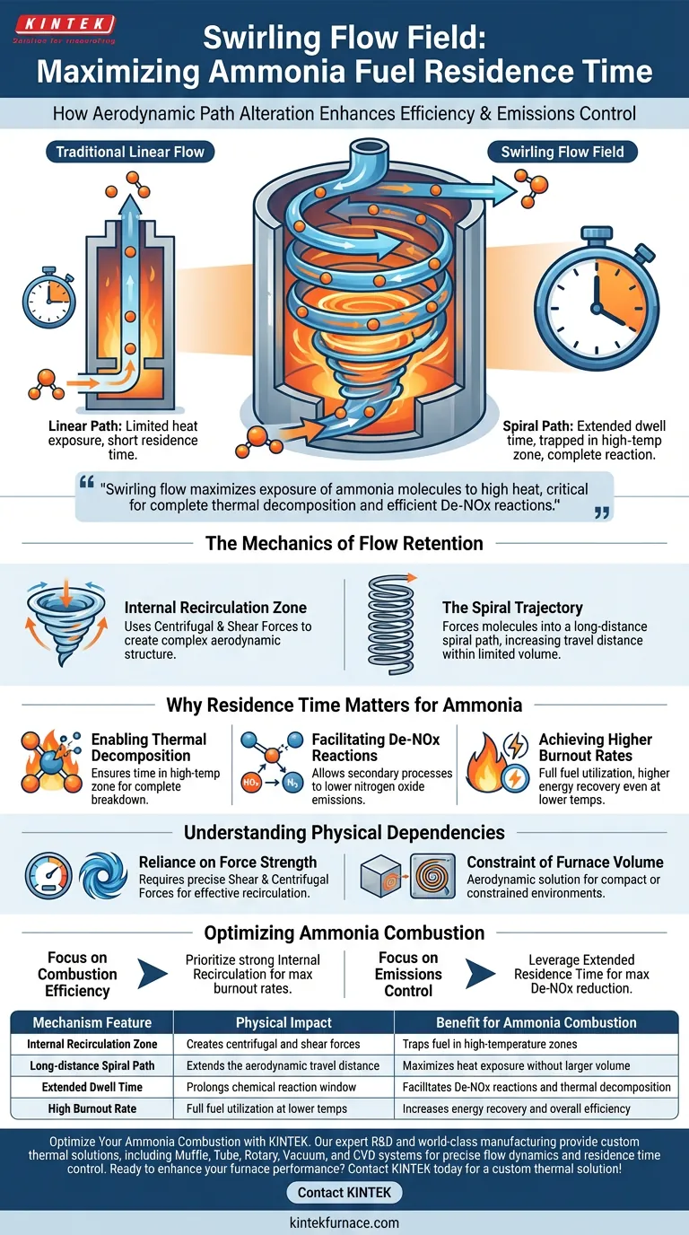
A swirling flow field dramatically extends residence time by fundamentally altering the aerodynamic path of pure ammonia fuel. Instead of traveling linearly, the fuel is subjected to intense centrifugal and shear forces that generate a strong internal recirculation zone. This forces the ammonia molecules into a long-distance spiral path, effectively trapping them within the high-temperature reaction zone for a significantly longer duration than traditional linear flow permits.
By converting a short linear path into a long spiral trajectory, swirling flow maximizes the exposure of ammonia molecules to high heat. This extended duration is critical for achieving complete thermal decomposition and enabling efficient De-NOx reactions within a limited furnace volume.
The Mechanics of Flow Retention
To understand how residence time is manipulated, one must look at the aerodynamic structure created by the swirling mechanism.
The Internal Recirculation Zone
The core mechanism relies on the application of centrifugal and shear forces. These forces do not merely push the fuel forward; they create a complex aerodynamic structure known as an internal recirculation zone.
The Spiral Trajectory
Within this zone, fuel molecules are prevented from exiting quickly. Instead, they are forced onto a long-distance spiral path. This geometric alteration effectively increases the travel distance of the fuel without requiring a physically larger furnace.
Why Residence Time Matters for Ammonia
Extending the time fuel spends in the furnace is not just about delay; it is a chemical necessity for pure ammonia combustion.
Enabling Thermal Decomposition
Ammonia requires a specific thermal window to break down effectively. The extended residence time ensures molecules remain in the high-temperature reaction zone long enough for complete thermal decomposition to occur.
Facilitating De-NOx Reactions
Beyond simple combustion, the time window allows for secondary chemical processes. The recirculation zone provides the necessary conditions for De-NOx reduction reactions, helping to lower nitrogen oxide emissions naturally during the combustion process.
Achieving Higher Burnout Rates
The ultimate result of this extended dwell time is efficiency. The system achieves higher burnout rates, ensuring fuel is fully utilized even if the average operating temperatures are lower than those required by traditional combustion methods.
Understanding the Physical Dependencies
While swirling flow offers significant advantages, it relies heavily on precise physical forces.
Reliance on Shear and Centrifugal Force
The system's effectiveness is strictly bound by the strength of the shear and centrifugal forces generated. If these forces are insufficient, the internal recirculation zone will not form correctly, and the spiral path will collapse into a linear one, negating the benefits.
The Constraint of Furnace Volume
This technique is specifically designed to overcome the limitations of limited furnace volume. It is an aerodynamic solution to a spatial problem, meaning its primary value is found in compact or constrained environments where physical expansion is not an option.
Optimizing Ammonia Combustion
When designing or evaluating furnace systems for pure ammonia, consider how flow dynamics align with your specific objectives.
- If your primary focus is Combustion Efficiency: Prioritize a strong internal recirculation zone to ensure the high burnout rates necessary for maximizing energy recovery.
- If your primary focus is Emissions Control: Leverage the extended residence time to maximize the window for De-NOx reduction reactions, reducing the need for post-combustion treatment.
By mastering the aerodynamics of the spiral path, you turn the physical constraint of time into a chemical advantage.
Summary Table:
| Mechanism Feature | Physical Impact | Benefit for Ammonia Combustion |
|---|---|---|
| Internal Recirculation Zone | Creates centrifugal and shear forces | Traps fuel in high-temperature zones |
| Long-distance Spiral Path | Extends the aerodynamic travel distance | Maximizes heat exposure without larger volume |
| Extended Dwell Time | Prolongs chemical reaction window | Facilitates De-NOx reactions and thermal decomposition |
| High Burnout Rate | Full fuel utilization at lower temps | Increases energy recovery and overall efficiency |
Optimize Your Ammonia Combustion with KINTEK
Is your lab or industrial process facing challenges with ammonia fuel efficiency and emission control? KINTEK provides the cutting-edge thermal solutions you need. Backed by expert R&D and world-class manufacturing, we offer Muffle, Tube, Rotary, Vacuum, and CVD systems—all of which can be customized to support advanced flow dynamics and precise residence time control.
Our lab high-temperature furnaces are designed to handle unique fuel requirements, ensuring you achieve complete thermal decomposition and superior burnout rates. Let our experts help you design a system tailored to your specific research or production goals.
Ready to enhance your furnace performance? Contact KINTEK today to discuss your custom thermal solution!
Visual Guide
References
- Lizhen Qin, Dong-Hoon Shin. Swirling Flameless Combustion of Pure Ammonia Fuel. DOI: 10.3390/en18123104
This article is also based on technical information from Kintek Furnace Knowledge Base .
Related Products
- Spark Plasma Sintering SPS Furnace
- Laboratory Muffle Oven Furnace with Bottom Lifting
- High Temperature Muffle Oven Furnace for Laboratory Debinding and Pre Sintering
- Custom Made Versatile CVD Tube Furnace Chemical Vapor Deposition CVD Equipment Machine
- 1200℃ Muffle Oven Furnace for Laboratory
People Also Ask
- Why is it necessary to maintain a high vacuum environment during the SPS of SiC? Key to High-Density Ceramics
- How does the heating mechanism of Spark Plasma Sintering (SPS) function? Enhance TiC/SiC Composite Fabrication
- What are the technical advantages of using an SPS sintering furnace? Elevate Al2O3-TiC Material Performance
- What are the steps in the discharge plasma sintering process? Master Fast, High-Density Material Consolidation
- What are the advantages of spark plasma sintering (SPS) over traditional forging? Precision Microstructural Control