To compensate for changes in MPCVD device parameters, you must adjust the frequency and phase of the microwave source. These two adjustments are the primary controls used to re-establish a stable and efficient plasma state after the physical or electrical characteristics of the reactor have been altered.
An MPCVD reactor is a finely-tuned resonant system. Any physical change—from adjusting the sample stage to thermal expansion during operation—alters its resonant frequency and impedance. Adjusting the microwave source's frequency and phase is the fundamental method for re-establishing resonance and ensuring maximum power is delivered to the plasma, not reflected back to the source.
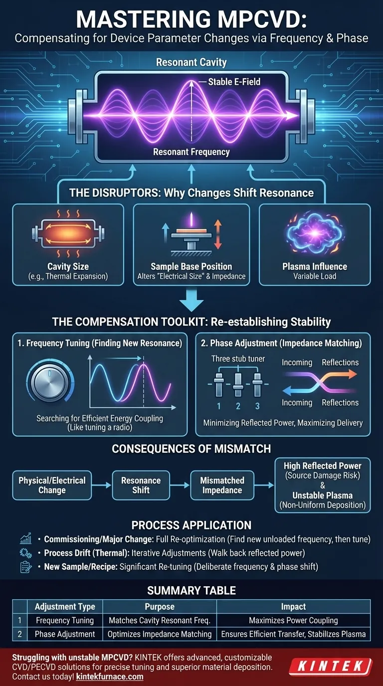
The MPCVD Reactor as a Resonant Cavity
To understand why these adjustments are critical, you must first view the MPCVD system not just as a chamber, but as a microwave resonant cavity, similar to the body of a musical instrument.
The Goal: A Stable Electric Field
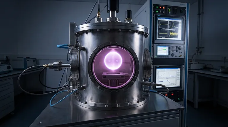
The core purpose of the microwave system is to generate a strong, stable, and spatially-confined electric field (E-field). It is this intense E-field that strips electrons from the process gas atoms, igniting and sustaining the plasma.
Achieving Resonance
A resonant cavity has a specific resonant frequency at which it stores energy most efficiently. When the microwave generator's frequency matches the cavity's resonant frequency, the waves inside reinforce each other, creating a powerful standing wave with a very high E-field intensity at a predictable location.
Why Physical Changes Demand Compensation
The resonant frequency of your cavity is not a fixed constant. It is highly sensitive to the physical and electrical conditions within it.
Impact of Cavity Size
The most direct influence on resonant frequency is the physical geometry of the cavity. Any change in the reactor's dimensions, whether intentional (swapping a part) or unintentional (thermal expansion), will shift the resonant frequency.
Impact of Sample Base Position
Introducing or moving any conductive or dielectric material, such as the sample stage or the substrate itself, alters the electromagnetic field distribution. This change in the internal field geometry effectively changes the "electrical size" of the cavity, thereby shifting its resonant frequency and changing its impedance.
The Plasma's Own Influence
The plasma itself has unique dielectric properties. Its size, density, and temperature are not static; they change dynamically during the process. This means the plasma acts as a variable load on the system, causing its own subtle but important shifts in resonance.
The Compensation Toolkit: Frequency and Phase
When a physical change causes a mismatch, power is reflected, and the plasma becomes inefficient or unstable. Frequency and phase are your tools to correct this.
Frequency Tuning: Finding the New Resonance
Adjusting the frequency of the microwave source is the direct way to compensate for a change in the cavity's resonant frequency. By sweeping the frequency, you are essentially "searching" for the new resonant peak where energy coupling is most efficient.
This is analogous to re-tuning a radio to a new station after the frequency has drifted. Your goal is to match the source frequency to the cavity's new natural frequency.
Phase Adjustment: Matching the Impedance
Adjusting the phase is about impedance matching. For maximum power to be transferred from the generator to the plasma, the impedance of the source must match the impedance of the plasma-filled cavity. Mismatches cause power to be reflected.
Phase shifters, often in the form of a 3-stub tuner, are used to cancel out these reflections. By adjusting the phase, you ensure that the power intended for the plasma is actually delivered to it.
Common Pitfalls and Consequences
Failing to properly compensate for system changes leads to predictable and detrimental outcomes.
The Consequence of Mismatch: Reflected Power
The most immediate consequence of a resonance and impedance mismatch is a spike in reflected power. This power does not enter the plasma; instead, it travels back up the waveguide to the microwave generator (magnetron or solid-state source), which can cause overheating and damage.
Plasma Instability and Non-Uniformity
An improperly tuned system leads to an unstable or incorrectly shaped plasma. This can manifest as a plasma ball that is dim, flickering, off-center, or improperly formed, directly resulting in non-uniform, low-quality material deposition.
Chasing a Moving Target
Remember that even during a stable run, the system is changing. As the reactor heats up, thermal expansion minutely alters the cavity dimensions, causing the resonant frequency to drift. This requires periodic or continuous automatic adjustments to maintain optimal conditions.
Applying This to Your MPCVD Process
Your approach to tuning should depend on your specific situation.
- If you are commissioning a new system or have changed a major component: You must perform a full re-optimization. Start by finding the new unloaded resonant frequency, then ignite the plasma and iteratively adjust both frequency and phase to minimize reflected power.
- If you are observing process drift or plasma instability during a run: The likely cause is thermal drift. Make small, iterative adjustments to frequency and/or phase to walk the reflected power back to its minimum.
- If you are adjusting the sample stage or substrate size for a new recipe: Expect a significant shift in resonance. This is not a small tweak; it requires a deliberate re-tuning of both frequency and phase to find the new optimal operating point.
Mastering this feedback loop between the system's physical state and the microwave source's parameters is the key to consistent and high-quality material deposition.
Summary Table:
| Adjustment Type | Purpose | Impact on MPCVD Process |
|---|---|---|
| Frequency Tuning | Matches cavity resonant frequency | Maximizes power coupling to plasma, reduces reflections |
| Phase Adjustment | Optimizes impedance matching | Ensures efficient power transfer, stabilizes plasma formation |
Struggling with plasma instability or inefficient MPCVD processes? KINTEK leverages exceptional R&D and in-house manufacturing to provide advanced high-temperature furnace solutions, including CVD/PECVD Systems. Our deep customization capabilities ensure precise tuning for your unique experimental needs, delivering stable plasma and superior material deposition. Contact us today to optimize your MPCVD setup!
Visual Guide
Related Products
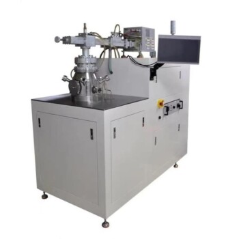
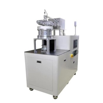
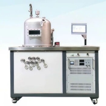
- Cylindrical Resonator MPCVD Machine System for Lab Diamond Growth
- MPCVD Machine System Reactor Bell-jar Resonator for Lab and Diamond Growth
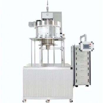
- 915MHz MPCVD Diamond Machine Microwave Plasma Chemical Vapor Deposition System Reactor
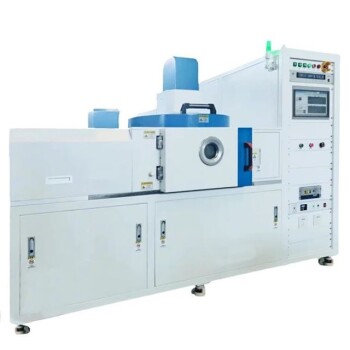
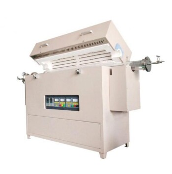
- Multi Heating Zones CVD Tube Furnace Machine for Chemical Vapor Deposition Equipment
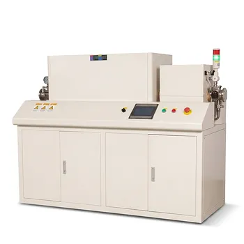
- Slide PECVD Tube Furnace with Liquid Gasifier PECVD Machine
People Also Ask
- What factors influence the quality of diamond deposition in the MPCVD method? Master the Critical Parameters for High-Quality Diamond Growth
- What are the essential components of an MPCVD reactor system? Build a Pristine Environment for High-Purity Materials
- How do carbon-containing groups contribute to diamond growth in the MPCVD method? Unlock High-Quality Diamond Synthesis
- What are the key components of an MPCVD system? Unlock High-Purity Crystal Growth
- How does MPCVD achieve stable temperature control during diamond growth? Master Precise Thermal Management