At the critical gel point, a single continuous solid network—the spanning cluster—instantaneously percolates the entire reaction vessel, locking in a pore architecture that physically dictates how solvents escape and how the material responds to heat. This structural transition is not gradual; it is a percolation event where growing silicate clusters link across macroscopic distances, causing viscosity to diverge and the system to exhibit solid-like elasticity. The cross-link density, branch topology, and pore tortuosity frozen at that moment determine the magnitude of capillary stresses and outgassing pressures the gel will endure during subsequent thermal processing. Therefore, designing a calcination profile is fundamentally an exercise in reading the gel’s microstructure: weakly branched, large-pore networks tolerate faster heating, while highly cross-linked, small-pore networks demand exceptionally slow, carefully staged ramps to avoid catastrophic cracking.
The precursor chemistry—acid/base catalysis and water ratio—defines the gel’s branching architecture at the point of percolation. That architecture, in turn, governs the maximum safe ramp rate, dwell temperatures, and atmosphere control needed during calcination. Misreading this relationship leads to violent outgassing, internal pressure spikes, and sintered bodies riddled with defects.
The Gel Point: From Sol to a Percolating Solid
What Happens Structurally at the Gel Point?
In the sol-gel process, hydrolysis and condensation build silicate oligomers that eventually grow into ramified clusters. As these clusters collide and link, they approach the percolation threshold. At that threshold, a single, sample-spanning cluster emerges—a fractal network that physically connects one end of the reaction vessel to the other. This is the gel point.
The moment the spanning cluster forms, the system’s rheology flips. Viscosity diverges, and the material acquires a measurable elastic modulus. From a structural perspective, the gel point freezes in the branching pattern and cross-link density that evolved under the specific synthesis conditions. The network that percolates is not a random, featureless solid; it is a snapshot of the cluster-cluster aggregation pathway, with an enormous internal surface area and a tortuous, interconnected pore labyrinth.
How Precursor Chemistry Maps to Network Architecture
The spanning cluster’s topology is not fixed—it is chemically tunable. Two parameters dominate:
-
Acid-catalyzed, low water-to-Si ratio (w): Hydrolysis outpaces condensation, producing weakly branched, almost linear polymeric clusters. When these percolate, the resulting gel has an open, large-pore structure with low cross-link density. The network is flexible, allowing significant shrinkage without fracture, and solvent can escape easily through the wide pore channels.
-
Base-catalyzed, high w: Condensation dominates, creating highly condensed, particulate clusters that resemble discrete spherical units. At the gel point, these particles pack into a dense, highly cross-linked network with extremely small pores and high tortuosity. This gel is stiffer, more brittle, and traps solvents in nanoscale constrictions.
Intermediate conditions yield moderately branched structures that sit between these two extremes. This direct mapping from synthesis to gel microstructure is the key to predicting thermal behavior.
Why the Gel’s Microstructure Dictates Calcination Hazards
Capillary Stress and Differential Shrinkage
As a gel dries, the liquid menisci inside pores generate capillary pressure inversely proportional to pore radius. In a small-pore particulate gel, capillary pressures can reach tens of megapascals, exerting a compressive force that collapses the network and causes severe shrinkage. If the outer surface dries faster than the interior, a dry skin forms, and subsequent shrinkage of the still-wet core creates tensile stresses that rip the gel apart.
A weakly branched, large-pore gel has dramatically lower capillary pressures. Shrinkage is more uniform and less violent. When designing a calcination profile, the first critical ramp—through the solvent’s boiling point—must be slow enough that the entire body loses solvent uniformly. For particulate gels, this often means rates of 0.1–1 °C/min, while polymeric gels can tolerate 2–5 °C/min or more.
Outgassing of Entrapped Solvent and Organics
The gel skeleton contains not just water but also residual alkoxy groups and organic templates. In a tight, tortuous network, these decomposition by-products cannot diffuse out quickly. Heating too fast causes internal pressure to spike, leading to blistering, exfoliation, or explosive fragmentation. The same pore architecture that resists solvent flow also throttles gas escape during organic burnout. A tailored profile thus inserts long dwells at temperatures where specific species evolve (e.g., 200–300 °C for residual alcohol, 400–500 °C for template decomposition) to allow diffusion-limited outgassing without structural failure.
Designing a Safe Thermal Calcination Profile
Matching Ramp Rates to Gel Architecture
The first principle is that ramp rate must scale inversely with cross-link density and pore tortuosity. A practical workflow:
- Characterize the gel’s architecture via nitrogen sorption or thermogravimetric analysis (TGA) of the dried xerogel.
- If the TGA shows a single, broad weight-loss event and large mesopores, the gel is likely weakly branched—opt for a moderate, continuous ramp.
- If weight loss occurs in sharp bursts and pores are microporous, the gel is highly cross-linked—segment the profile into a series of ultra-slow ramps (0.2–1 °C/min) separated by extended dwells.
In high-performance laboratory furnaces, you can program multi-step profiles that hold at each critical temperature zone until off-gassing subsides.
Atmosphere Control During Sintering
The calcination atmosphere must match the gel’s chemistry and end goal:
- Oxidative atmosphere (air or O₂ flow): Necessary to burn out organic residues. A too-rapid oxidation of residual carbon in a tight network can cause a localized exotherm—an internal “hot spot” that cracks the piece. Controlled, lean oxygen flow combined with slow heating prevents runaway combustion.
- Inert atmosphere (N₂ or Ar): Used when preserving carbon in the final ceramic (e.g., oxycarbide glasses) or when sintering non-oxide ceramics. Here, thermal decomposition is slower but still generates gaseous species needing an escape path.
- Vacuum or reducing atmospheres: For specialized applications, but they exacerbate outgassing by removing the ambient gas that might otherwise dampen internal pressure differences.
Critical Temperature Zones
Every calcination profile must recognize at least three regimes:
- Ambient to ~200°C: Removal of physisorbed water and volatile solvents. Slow ramps prevent skinning and bubble formation.
- 300–500°C: Decomposition of organic templates and residual alkoxy groups. This zone often requires the longest dwells, as diffusion is the bottleneck.
- Above 600°C: Sintering and collapse of residual porosity. Ramp rates can often increase here because the pore structure is already partially collapsed, but excessive speed can still cause differential densification and warping.
Understanding the Trade-offs
The price of a perfectly crack-free monolith is time. A gel that demands a 0.2 °C/min ramp over a 12-hour burn-out cycle ties up a furnace and increases energy costs. Pushing the rate to save time risks a failure rate that negates any efficiency gain. Additionally, some architectures that yield the densest final ceramics (highly branched particulate gels) are inherently the most difficult to fire. The process engineer must balance microstructural control against throughput. Another pitfall: assuming a single generic profile works for all gels. Even minor shifts in hydrolysis pH or aging time alter the percolation network enough to change safe ramp rates. Without TGA or DSC verification, a “standard” profile is a gamble.
How to Apply This to Your Calcination Process
- If your primary focus is a crack-free, dense ceramic: Begin with a base-catalyzed, high-w particulate gel, but design the calcination profile with ultra-slow ramps (≤0.5 °C/min) and extended dwells at 200 °C, 400 °C, and 550 °C, using flowing air to gently oxidize organics.
- If your primary focus is a thick film or fiber where flexibility and fast processing matter: Choose an acid-catalyzed, low-w weakly branched gel, and ramp at 3–5 °C/min with a single short dwell at the solvent boiling point—this architecture forgives faster heating.
- If your primary focus is a porous scaffold (e.g., for catalysis): Tailor the intermediate branching to fix the desired pore size, then use a thermal profile that stops short of full densification, ramping slowly only through the organic burnout zone.
The gel point is not just a rheological curiosity; it is the instant the final ceramic’s sintering history is set. Your furnace profile succeeds when it reads that history and responds with precisely the thermal patience the network demands.
Summary Table:
| Gel Architecture | Microstructure Characteristics | Thermal Outgassing & Stress Risk | Calcination Profile Strategy |
|---|---|---|---|
| Acid-Catalyzed (Low w) | Weakly branched, large mesopores, low cross-linking | Low capillary stress, easy solvent escape | Moderate ramps (2–5 °C/min), short solvent dwell |
| Base-Catalyzed (High w) | Highly cross-linked, microporous, high tortuosity | High capillary pressure, severe cracking/outgassing risk | Ultra-slow ramps (0.1–1 °C/min), multi-stage extended dwells |
| Intermediate | Moderately branched particulate networks | Moderate stress & localized exotherm risks | Segmented heating, atmosphere-controlled organic burnout |
Master Precise Thermal Processing for Complex Sol-Gel Materials with KINTEK
Prevent structural defects, cracking, and violent outgassing by equipping your laboratory with industry-leading thermal processing systems. KINTEK specializes in high-performance laboratory equipment and high-temperature furnaces—including highly customizable muffle, tube, atmosphere, vacuum, CVD, rotary, and induction melting furnaces—engineered to deliver the exact multi-segment ramp control and atmosphere regulation your gel architectures demand.
Whether you require ultra-slow heating rates (≤0.2 °C/min) or precise oxygen-flow environments for organic burnout, our customizable lab high-temp furnaces ensure optimal density and crack-free results for all your synthetic ceramics.
Contact KINTEK Thermal Experts Today to configure the ideal furnace for your sol-gel calcination workflow!
Related Products
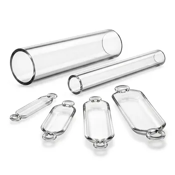
- High Purity Quartz Tube and Quartz Boat for Laboratory Furnaces
- Small Vacuum Heat Treat and Tungsten Wire Sintering Furnace
- High Temperature Muffle Oven Furnace for Laboratory Debinding and Pre Sintering
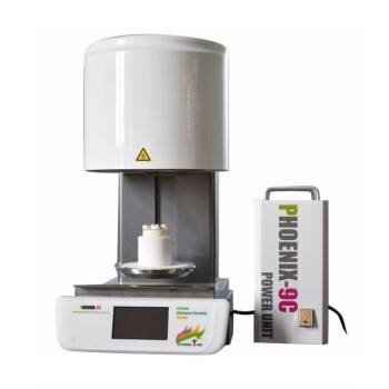
- Vacuum Dental Porcelain Sintering Furnace for Dental Laboratories
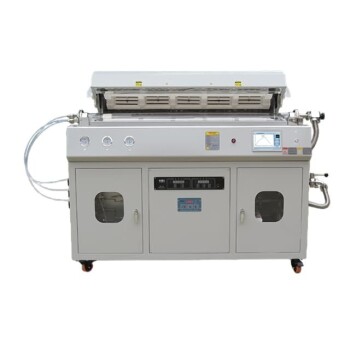
- Multi Heating Zones CVD Tube Furnace Machine for Chemical Vapor Deposition Equipment
People Also Ask
- What tube furnace protocols prevent hydrogen embrittlement in Pd membranes? Safe Heating Guide
- What parameters must be controlled when calcining freeze-dried oxide precursors in a laboratory tube furnace? A Guide
- Why is precise atmosphere control in a laboratory tube furnace required when evaluating palladium membranes?
- What is the relationship between chemical hydrolysis of metal alkoxides and lab tube furnace thermal processing?
- How does pore size influence pore mobility and boundary breakaway during the high-temperature sintering of ceramic compacts in laboratory furnaces?