Cold consolidation forces free dislocations to reorganize into thermally stable boundary networks. This defect transition directly dictates your annealing and sintering hold points.
During the first consolidation stage—dominated by particle rearrangement and initial plastic yielding—iron powder compacts generate a massive population of free volume dislocations and rapidly reduce crystallite size. As pressing pressure enters the second stage (bulk plastic flow), that crystallite fragmentation slows, and the free dislocations migrate, entangle, and lock into stable, low-energy network configurations at grain and subgrain boundaries. Because boundary‑network dislocations demand a significantly higher thermal activation energy to recover than free dislocations, a furnace sintering profile must include a strategically placed intermediate temperature hold to reorganize these walls before full densification. Without that hold, the compact retains a high internal defect energy that will drive uncontrolled grain growth, prevent pore elimination, and compromise final density.
The defect story of iron green compacts is a two‑act transition: first, a burst of easily recovered free dislocations; second, the creation of stable boundary dislocation networks that refuse to heal without a dedicated thermal recovery window. A sintering protocol that ignores this transition inevitably locks in structural flaws.
The Two Consolidation Stages and Their Defect Signatures
First Stage: Particle Slipping Produces a Cloud of Free Dislocations
In the early pressing regime (roughly up to 245–480 MPa for iron), the dominant compaction mechanism is particle rearrangement and localized yielding at contact points. Individual particles slide, rotate, and bridge gaps under mechanical shear.
This cold work generates three parallel structural changes: a sharp reduction in crystallite size, a surge in point defects, and a high density of free volume dislocations—isolated dislocations not yet tied into organized patterns. These free dislocations are highly mobile and highly energetic. They represent a steep energy gradient stored in the green compact’s crystal lattice, waiting to be released the moment thermal energy becomes available.
Second Stage: Plastic Flow Transforms Free Dislocations into Boundary Networks
Once the particle bed locks into a contiguous skeleton, further densification must come from bulk plastic flow of the metal particles (up to ~1000 MPa). The deformation shifts from simple slip between particles to full‑scale dislocation glide, climb, and multiplication within each grain.
During this stage, two critical defect transitions occur simultaneously. Crystallite size reduction plateaus, and the vast population of free dislocations begins to rearrange. Dislocations migrate to low‑energy positions at grain and subgrain boundaries, forming dense dislocation networks and tangles that pin the lattice. These boundary networks are thermodynamically more stable than free dislocations. Their recovery—untangling and annihilation—requires a larger thermal energy input because the dislocations have already minimized their strain fields through mutual arrangement.
In essence, the first stage creates a storm of easily healed defects; the second stage builds a defect architecture that is stubbornly resistant to low‑temperature annealing.
How the Defect Transition Reshapes Sintering Protocol Design
Free Dislocations Recover Quickly, Boundary Networks Demand a Dedicated Hold
When a green compact enters a continuous sintering furnace, the free volume dislocations produced during the first consolidation stage can be efficiently annihilated at relatively low temperatures—often during the early de‑bind or outgassing ramp. Their recovery consumes minimal time and does not require a deliberate soak.
The boundary dislocation networks, however, are an entirely different challenge. They survive well into the intermediate temperature range. To reorganize these walls without triggering rapid grain growth or pore closure, the thermal profile must incorporate a controlled recovery hold at an intermediate temperature, typically just below the onset of recrystallization. This allows dislocation climb and cross‑slip to transform the tangled networks into more ordered, low‑angle boundaries that can later vanish gracefully during high‑temperature sintering.
Without Recovery, Stored Defect Energy Drives Unwanted Grain Growth
If the furnace ramps directly from low‑temperature burnout to full sintering without a recovery stage, the energy locked in the boundary dislocation networks becomes a liability. Once the thermal activation threshold is crossed, that stored energy feeds exaggerated grain coarsening rather than controlled densification. The result is a body that may look dense but has a coarse microstructure with trapped intragranular pores—defects that no subsequent heat treatment can easily remove.
Open Pore Stage Timing Must Align with Dislocation Recovery
During the intermediate sintering stage, the compact maintains an interconnected pore network with open channels to the atmosphere. This is both an opportunity and a pressure point. Furnace atmosphere can freely enter or leave the compact, making it the ideal window for chemical reduction and outgassing. If the dislocation recovery hold is placed within this open‑pore temperature regime, the furnace gas can simultaneously assist in reducing any residual oxide films that survived pressing while the boundary networks restructure.
Placing the recovery hold too late—when the compact is already closing its surface pores—risks sealing process gases inside, while leaving the boundary networks partially stabilized. This combination is a classic root cause of bloat, internal fissures, and arrested densification in iron powder metallurgy parts.
Understanding the Trade-offs in Thermal Profile Design
The Cost of Time vs. the Price of Defects
Inserting an intermediate recovery hold increases total furnace cycle time. Production‑oriented operations are often tempted to eliminate it. The trade‑off is clear: a faster cycle yields higher throughput, but at the risk of inconsistent mechanical properties, lower sintered density, and microstructural flaws that may only surface during service.
For critical structural components (e.g., gears, bearing races, or magnetic flux path elements), the defect penalty of skipping the recovery hold far outweighs the productivity gain.
Green Density Variability Magnifies the Need for Adaptive Schedules
Not all iron powder compacts experience the same distribution of free versus network dislocations. Higher green densities—achieved by aggressive second‑stage pressing—produce proportionally more stable boundary networks. A single “recipe” thermal profile may therefore fail when green density varies from batch to batch.
The sintering furnace protocol must be validated for the highest green density scenario in the process window. If the hold time and temperature are set for that condition, lower‑density parts will still sinter correctly; the reverse is not true.
Oxide Films and Localized Bonds Influence Defect Healing Pathways
During pressing, particle friction shears off surface oxide layers and creates localized mechanical bonds. These clean metallic contacts are essential for initial neck formation. However, the same friction‑generated cold work injects additional dislocations near the particle surfaces.
When the recovery hold is correctly positioned, these surface‑adjacent dislocations are among the first to reorganize, enabling uniform transport during the subsequent intermediate‑stage sintering. If the oxide removal was incomplete, the defect networks may be pinned by oxide inclusions, demanding a slightly higher recovery temperature or a longer dwell to achieve the same structural relaxation.
Making the Sintering Protocol Work for Your Iron Powder Compact
Achieving a fully dense, fine‑grained part with minimal internal stress requires aligning the furnace thermal profile with the two‑stage defect evolution during consolidation.
- If your primary focus is maximum sintered density: Include a dedicated intermediate temperature hold (often in the 400–600 °C range for iron) to reorganize boundary dislocation networks while the pore network is still open, then ramp to final sintering temperature. This prevents stored defect energy from converting into grain coarsening and shuts down pore‑isolating instabilities.
- If your primary focus is minimizing process time: Audit whether your final application truly demands a full recovery step. For non‑structural, low‑stress parts, you may shorten or eliminate the hold, but validate the trade‑off with statistical testing of mechanical properties and pore morphology.
- If your primary focus is handling green density variation: Synchronize the recovery hold with the highest green density expected in production. Use an in‑line density check to flag outliers and adjust the hold duration dynamically, ensuring the most defect‑intensive compacts receive adequate thermal healing without over‑soaking lower‑density parts.
Control the recovery of that second‑stage defect architecture, and you control the final quality of the entire sintering operation—no matter what your pressing line throws at you.
Summary Table:
| Consolidation Stage | Primary Mechanism | Defect Signature | Thermal Recovery Characteristics | Sintering Protocol Requirement |
|---|---|---|---|---|
| First Stage (Up to ~245–480 MPa) | Particle rearrangement & localized shear | Free volume dislocations & crystallite size reduction | Mobile & high energy; recovers at low temperatures | Easily annihilated during initial burnout/de-bind ramp |
| Second Stage (Up to ~1000 MPa) | Bulk plastic flow & dislocation glide/climb | Boundary dislocation networks & tangles | Stable & pinned; requires high thermal activation energy | Requires dedicated intermediate recovery hold (e.g., 400–600 °C) prior to full densification |
Achieve Perfect Sintered Density with KINTEK High-Temperature Furnaces
Eliminating defect-driven microstructural flaws requires precise, multi-stage thermal profile control and reliable atmosphere management. At KINTEK, we specialize in high-performance laboratory equipment and consumables tailored for advanced powder metallurgy and materials research.
Our extensive selection of customizable high-temperature lab furnaces—including atmosphere, vacuum, tube, muffle, rotary, CVD, dental, and induction melting furnaces—delivers the exact temperature uniformity and hold precision required to reorganize boundary dislocation networks and maximize final part density.
Take control of your thermal processing. Contact KINTEK today to discuss your custom furnace solution with our metallurgy experts!
Related Products
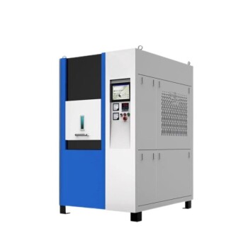
- Spark Plasma Sintering SPS Furnace
- Small Vacuum Heat Treat and Tungsten Wire Sintering Furnace
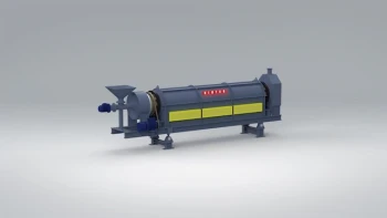
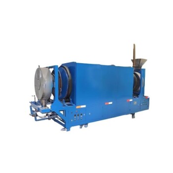
- Electric Rotary Kiln Small Rotary Furnace for Activated Carbon Regeneration
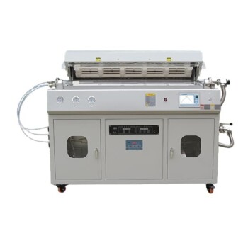
- Multi Heating Zones CVD Tube Furnace Machine for Chemical Vapor Deposition Equipment
- High Temperature Muffle Oven Furnace for Laboratory Debinding and Pre Sintering
People Also Ask
- How does the heating mechanism of Spark Plasma Sintering (SPS) function? Enhance TiC/SiC Composite Fabrication
- Why is it necessary to maintain a high vacuum environment during the SPS of SiC? Key to High-Density Ceramics
- What are the technical advantages of using an SPS sintering furnace? Elevate Al2O3-TiC Material Performance
- What are the steps in the discharge plasma sintering process? Master Fast, High-Density Material Consolidation
- What are the advantages of spark plasma sintering (SPS) over traditional forging? Precision Microstructural Control