A Plasma-Enhanced Chemical Vapor Deposition (PECVD) system is a complex instrument defined by the precise capabilities of its core subsystems. Key specifications revolve around its power generators for creating plasma, the process chamber for hosting the reaction, a high-performance vacuum system for controlling the environment, and sophisticated gas delivery and thermal management systems.
A PECVD system's specifications are not merely a list of numbers; they represent an integrated set of tools for controlling a plasma-driven chemical reaction. Understanding how the power, vacuum, gas, and thermal systems interact is the true key to controlling the properties of your deposited thin films.
The Core Process Chamber
The chamber is the heart of the PECVD system, where the deposition process occurs. Its design directly impacts uniformity, throughput, and the types of materials you can process.
Substrate and Electrode Configuration
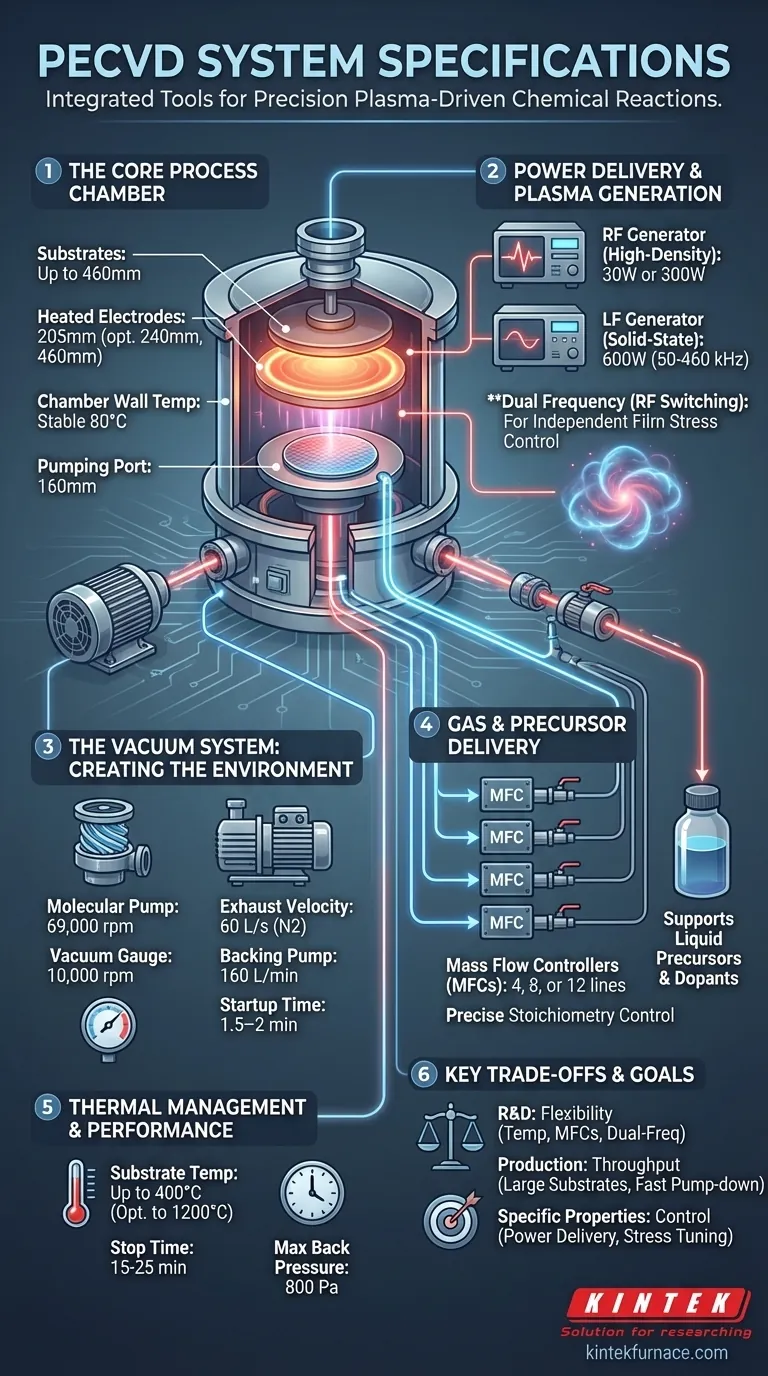
The system accommodates substrates, or wafers, up to 460 mm in diameter.
It features a heated upper electrode and a 205 mm electrically heated lower electrode. Optional electrode sizes of 240 mm and 460 mm are available to match different substrate requirements.
Chamber Environment Control
The chamber walls are heated to a stable 80°C to prevent unwanted deposition and ensure process repeatability. The chamber body includes a large 160 mm pumping port for efficient evacuation.
Power Delivery and Plasma Generation
The power delivery system is what transforms inert gases into a reactive plasma. The choice of frequency and power level is one of the most critical factors in determining film properties.
Radio Frequency (RF) Generator
An RF generator, with selectable power outputs of 30 W or 300 W, is used to generate a high-density plasma. This is the primary driver for the deposition reaction.
Low Frequency (LF) Generator
A 600 W solid-state Low Frequency (LF) generator is also included, operating in a range of 50-460 kHz.
The Role of Dual Frequencies
The ability to switch between or mix RF and LF power, known as RF switching, is a crucial feature. It provides an independent mechanism for controlling the ion bombardment energy, which is used to manage and tune the internal stress of the deposited film.
The Vacuum System: Creating the Environment
A clean, controlled, low-pressure environment is non-negotiable for high-quality film deposition. The vacuum system is designed for rapid pump-down and maintaining high vacuum levels.
Pumping Capabilities
The high-vacuum system is built around a molecular pump operating at 69,000 rpm. This pump provides exhaust velocities of 60 L/s for Nitrogen (N2) and 55 L/s for N2 when using a protective net.
It achieves high compression ratios of 2x10^7 for N2 and 3x10^3 for H2, ensuring a very low base pressure. The pump utilizes ceramic bearings with a service life of 20,000 hours.
Backing Pump and System Integration
A two-stage rotary vane vacuum pump with a 160 L/min exhaust speed serves as the backing pump. The entire system is managed by a TC75 molecular pump controller.
System Performance Metrics
The system has a startup time of 1.5–2 minutes and a stop time of 15–25 minutes. It is designed to handle a maximum allowable back pressure of 800 Pa.
Gas and Precursor Delivery
Precise control over the flow of reactant gases and chemical precursors is fundamental to achieving the desired film stoichiometry and properties.
Mass Flow Controllers (MFCs)
The system can be configured with 4, 8, or 12 gas lines, each independently regulated by a mass flow controller (MFC). This allows for precise and repeatable mixing of different process gases.
Precursor Options
The system supports the use of various dopants and liquid precursors, expanding the range of materials that can be deposited.
Understanding Key Specifications and Their Trade-offs
Choosing or operating a PECVD system involves balancing competing factors. A specification that is ideal for one application may be a limitation for another.
Power vs. Film Properties
High RF power generally increases the deposition rate but can also lead to higher film stress or potential substrate damage. The addition of LF power provides a tool to mitigate this stress, but it requires careful tuning to avoid compromising other film qualities like density.
Temperature vs. Throughput
Higher substrate temperatures (up to 400°C, with options to 1200°C) often improve film quality, density, and adhesion. However, this comes at the cost of longer heating and cooling cycles, reducing throughput. It also limits the types of substrates that can be used.
Pumping Speed vs. Cost and Complexity
A faster pumping speed allows for quicker cycle times and a lower base pressure, which improves film purity. However, larger and more powerful pumps increase the system's cost, footprint, and maintenance requirements.
Matching System Specifications to Your Deposition Goals
Your specific application should dictate which specifications you prioritize.
- If your primary focus is research and development (R&D): Prioritize flexibility, such as a wide substrate temperature range, a large number of MFC gas lines, and dual-frequency RF/LF generators for process tuning.
- If your primary focus is high-throughput production: Emphasize features like large substrate handling (460 mm), fast pump-down and venting times, and robust automation with in-situ cleaning and endpoint control.
- If your primary focus is specific material properties (e.g., low-stress films): Pay close attention to the power delivery system, ensuring it has dual-frequency capabilities and parameter ramping software for fine control over the deposition process.
Ultimately, understanding these specifications empowers you to select or operate a PECVD system as a precision instrument tailored to your specific material science objectives.
Summary Table:
| Specification Category | Key Details |
|---|---|
| Process Chamber | Substrates up to 460 mm, heated electrodes (205-460 mm), wall temp 80°C, 160 mm pumping port |
| Power Delivery | RF: 30W/300W, LF: 600W (50-460 kHz), dual-frequency RF switching for stress control |
| Vacuum System | Molecular pump (69,000 rpm, 60 L/s N2), backing pump (160 L/min), base pressure < 1E-6 Torr, pump life 20,000 hours |
| Gas Delivery | 4-12 MFC lines, supports liquid precursors for precise stoichiometry |
| Thermal Management | Substrate temp up to 400°C (option to 1200°C) |
| Performance Metrics | Startup time 1.5-2 min, stop time 15-25 min, max back pressure 800 Pa |
Ready to enhance your lab's thin-film deposition capabilities? KINTEK specializes in advanced high-temperature furnace solutions, including PECVD systems tailored for R&D and production needs. With our strong R&D and in-house manufacturing, we offer deep customization to meet your unique experimental requirements—from precise power control to optimized vacuum and gas delivery. Contact us today to discuss how our expertise can drive your material science innovations forward!
Visual Guide
Related Products
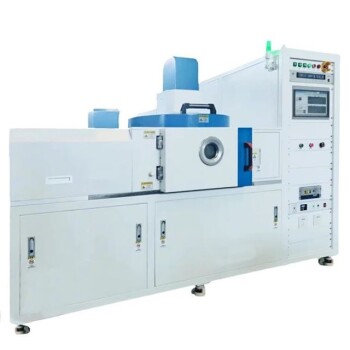
- RF PECVD System Radio Frequency Plasma Enhanced Chemical Vapor Deposition
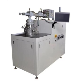
- Slide PECVD Tube Furnace with Liquid Gasifier PECVD Machine
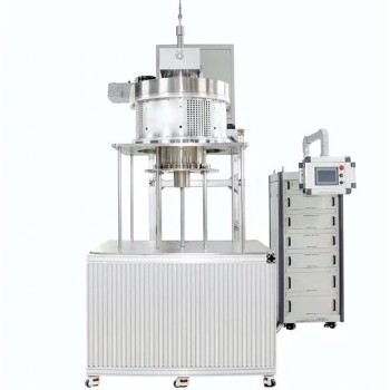
- Inclined Rotary Plasma Enhanced Chemical Deposition PECVD Tube Furnace Machine
- Inclined Rotary Plasma Enhanced Chemical Deposition PECVD Tube Furnace Machine
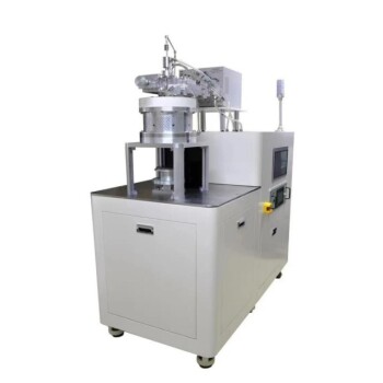
- Cylindrical Resonator MPCVD Machine System for Lab Diamond Growth
People Also Ask
- What is RF in PECVD? A Critical Control for Plasma Deposition
- What are some promising applications of PECVD-prepared 2D materials? Unlock Advanced Sensing and Optoelectronics
- What are the key advantages of PECVD technology? Achieve Low-Temperature, High-Quality Thin Film Deposition
- How is silicon dioxide deposited from tetraethylorthosilicate (TEOS) in PECVD? Achieve Low-Temperature, High-Quality SiO2 Films
- What are the advantages of PECVD in film deposition? Achieve Low-Temp, High-Quality Coatings