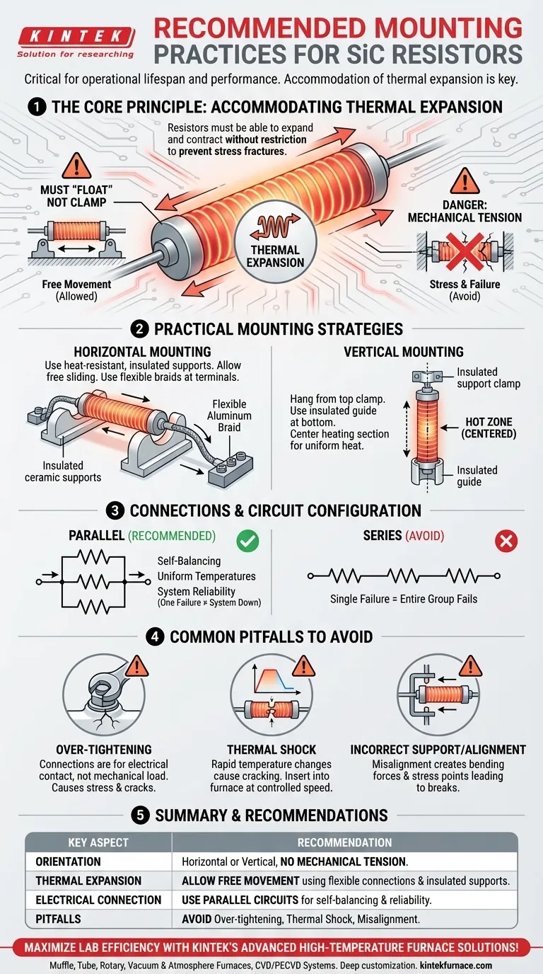
Properly mounting Silicon Carbide (SiC) resistors is critical for their operational lifespan and performance. The fundamental rule is that they can be installed either horizontally or vertically, but they must never be placed in mechanical tension. This ensures the elements have the freedom to expand and contract with temperature changes, preventing stress fractures and premature failure.
The primary goal of any SiC mounting strategy is to accommodate thermal expansion. Unlike metals, SiC is a brittle ceramic that will break, not bend, if its natural expansion and contraction are restricted. Successful mounting is less about rigid support and more about allowing controlled movement.
The Core Principle: Accommodating Thermal Expansion
Silicon Carbide resistors change in length as they heat up and cool down. Acknowledging this physical reality is the foundation of all correct mounting procedures.
Why SiC Resistors Must "Float"
At operating temperatures, a SiC heating element will be physically longer than when it is cold. The mounting system must allow for this growth without creating stress.
Think of the resistor as being cradled, not clamped. Holding it rigidly at both ends creates immense internal tension as it heats and tries to expand, inevitably leading to a fracture.
The Danger of Mechanical Tension
Any force that pulls on the resistor or prevents its free movement is considered mechanical tension. This is the single most common cause of premature element failure.
This stress can be introduced by over-tightened terminal connections, misaligned support brackets, or a system that does not account for the element's growth in length.
Practical Mounting and Connection Strategies
Whether you choose a horizontal or vertical orientation, the principle of allowing free movement remains the same.
Horizontal Mounting
When mounting horizontally, the resistor should rest on electrically insulated, heat-resistant supports. The element must be able to slide freely on these supports as it expands and contracts.
The connections at the ends should use flexible braids, such as aluminum, to allow for this movement without stressing the terminals.
Vertical Mounting
For vertical mounting, the element hangs from a support clamp. This clamp must not put the element in tension and should be paired with an insulated guide at the bottom.
Crucially, the hot, or heating, section of the resistor must be centered within the furnace chamber. This ensures uniform heat distribution and prevents localized overheating of the furnace walls or the element itself.
Why Parallel Connections Are Superior
SiC resistors should be connected in parallel whenever possible. This configuration provides a significant reliability advantage.
In a parallel circuit, elements with slightly lower resistance will initially draw more current and heat up faster. As their temperature rises, so does their resistance, naturally diverting current to the other elements. This creates a self-balancing system that promotes uniform temperatures and element aging. In a series circuit, the failure of one element disables the entire group.
Common Pitfalls to Avoid
Avoiding simple mistakes during installation is as important as following the correct procedures. These errors are often the root cause of unexpected failures.
Pitfall 1: Over-Tightening Connections
Spring clips and terminal connections are designed to ensure good electrical contact, not to bear a mechanical load. Overtightening them can restrict thermal expansion and crack the resistor's "cold end."
Pitfall 2: Causing Thermal Shock
SiC is a ceramic and is susceptible to thermal shock—cracking caused by a rapid, uneven change in temperature.
When replacing an element in a hot furnace, it must be inserted at a controlled, steady speed. Inserting it too quickly can cause it to crack. Inserting it too slowly can cause the aluminum at the terminals to melt before the element is fully in place.
Pitfall 3: Incorrect Support and Alignment
Ensure all support structures are properly aligned and made of appropriate electrically insulating materials. A misaligned support can introduce a bending force or "point load" on the resistor, creating a stress point that will eventually become a break.
Making the Right Choice for Your System
Your installation choices directly impact the reliability and efficiency of your heating process. Use this checklist to guide your decisions.
- If your primary focus is maximum element lifespan: Ensure the resistor is never in tension and can move freely as it heats and cools.
- If your primary focus is uniform furnace heating: Center the heating section of the resistor within the chamber and use a parallel electrical circuit.
- If your primary focus is system reliability: Use parallel electrical connections so that the failure of a single element does not shut down the entire heating system.
By treating the mounting process as a way to manage thermal forces, you ensure the long-term reliability and performance of your heating system.
Summary Table:
| Key Aspect | Recommendation |
|---|---|
| Mounting Orientation | Horizontal or vertical, with no mechanical tension |
| Thermal Expansion | Allow free movement using insulated supports or flexible connections |
| Electrical Connections | Use parallel circuits for self-balancing and reliability |
| Common Pitfalls | Avoid over-tightening, thermal shock, and misalignment |
Maximize your lab's efficiency with KINTEK's advanced high-temperature furnace solutions! Leveraging exceptional R&D and in-house manufacturing, we provide diverse laboratories with reliable SiC resistor systems, including Muffle, Tube, Rotary Furnaces, Vacuum & Atmosphere Furnaces, and CVD/PECVD Systems. Our strong deep customization capability ensures precise alignment with your unique experimental needs, enhancing performance and lifespan. Contact us today to discuss how we can optimize your heating processes!
Visual Guide
Related Products
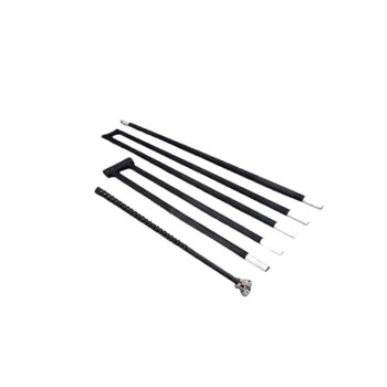
- Silicon Carbide SiC Thermal Heating Elements for Electric Furnace
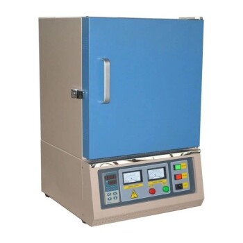
- 1400℃ Muffle Oven Furnace for Laboratory
People Also Ask
- What are the advantages of using silicon carbide heating elements in industrial furnaces? Boost Efficiency and Durability
- What are some common types of silicon carbide heating elements? Explore Shapes, Coatings, and High-Temp Performance
- What are the advantages of silicon carbide heating elements? Superior High-Temp Performance & Durability
- What is the recommended surface load for silicon carbide heating elements at different furnace temperatures? Maximize Lifespan & Performance
- What are the temperature capabilities and mounting options for silicon carbide heating elements? Unlock High-Temp Flexibility and Durability