If you ignore hysteresis and ink-bottle pore geometry, your debinding recipe is a gamble. The presence of ink-bottle pores—cavities connected by narrow necks—means that volatile binder breakdown products and trapped gases cannot easily escape during rapid heating. This can cause internal pressure spikes that crack, swell, or ruin the ceramic part. Designing furnace thermal profiles around these pore constraints is therefore not just good practice; it is essential to transition from a “black art” to a predictable, defect-free result.
Ink-bottle pores trap decomposition gases behind narrow constrictions, creating a risk of catastrophic pressure buildup during heating. A deep understanding of this pore architecture, revealed by adsorption hysteresis, directly dictates the critical slow-ramp and hold segments that must be built into every thermal profile to safely evacuate the furnace load.
The Hidden Architecture of the Green Body
The Ink-Bottle Pore Phenomenon
An ink-bottle pore consists of a large internal cavity connected to the surface only through a much narrower neck. During mercury porosimetry or gas adsorption, this geometry creates a classic hysteresis loop: adsorption fills the wide body at a specific relative pressure, but desorption cannot empty it until the pressure drops low enough to evaporate the liquid from the confining neck.
In debinding, that neck becomes a molecular gatekeeper. Binder molecules must travel from the deep interior of the pore network, through these restricted openings, to escape the part. If the neck radius is in the mesoporous range (2–50 nm), the pathway is constricted.
The hysteresis loop itself is a fingerprint of this risk. A wide hysteresis loop, especially one that persists to low relative pressures, flags a high density of these restrictive pore architectures.
How Standard Characterization Reveals the Danger
A nitrogen adsorption isotherm’s Type IV shape with a pronounced H2 hysteresis loop is the classic warning sign. The H2 loop confirms the ink-bottle morphology. The desorption branch’s steep collapse happens when the pore neck finally empties, pinning the liquid meniscus inside the body.
Without this data, a thermal profile is built blind. With it, you know that the debinding ramp rates must be calibrated to the escape kinetics through that narrowest constriction.
Designing the Thermal Profile Around Pore Constraints
The Physics of Internal Pressure Buildup
As temperature rises, the binder decomposes into low-molecular-weight volatiles. These gases must migrate through the pore network. At the ink-bottle neck, flow is restricted by Knudsen diffusion or surface diffusion limitations.
If gas generation outpaces gas escape, local pressure rises inside the large cavities. This is analogous to inflating a balloon inside a bottle with a corked neck: once pressure exceeds the crack-opening stress of the green ceramic, the part fails—often explosively, but sometimes through subtle microcracks that only appear after sintering.
Thermal profiles must therefore keep the decomposition rate below the critical transport threshold imposed by the smallest neck radius in the dominant pore population.
Translating Hysteresis Data into Hold Segments
A well-designed profile inserts dedicated low-temperature holds precisely where the binder decomposition kinetics peak. The key is to align these holds with the mass loss regions identified by thermogravimetric analysis (TGA), but to slow the ramp before the peak.
Because ink-bottle pore necks control the desorption step, they also control the effective escape time constant. A large hysteresis loop signals that the escape pathway is choked; the hold time must be extended accordingly. Think of it as giving the part a long enough breath to exhale the volatiles without straining.
The Role of Atmosphere and Partial Pressure
The atmosphere inside the furnace—whether flowing air, inert gas, or vacuum—interacts with the ink-bottle constraints. A vacuum furnace, for example, provides a large pressure gradient that can help pull gases out, but it also can make the volatile removal aggressive.
If the pore neck is very narrow, aggressive vacuum might actually cause sudden, violent degassing that damages the part. A partial-pressure atmosphere can moderate the escape rate, acting as a buffer. The hysteresis data informs this choice as well: a severe ink-bottle structure often benefits from a gentler, laminar-flow purge rather than a hard vacuum.
Understanding the Trade-offs
The Safety Margin vs. Cycle Time Penalty
The most obvious trade-off is time. A profile designed to protect against ink-bottle pressures is inherently slow. Long holds and shallow ramps stretch cycle times, which can throttle furnace throughput and raise cost per part.
You are essentially spending time to buy safety. For high-value ceramic components, this is non-negotiable. For high-volume, low-margin parts, the temptation to push the cycle faster can be strong. The hysteresis data gives you the objective rationale to defend the necessary holds instead of guessing.
The Risk of Over-Engineering the Profile
Just because an ink-bottle structure exists does not mean it always controls the failure mechanism. In some binders, decomposition gases are highly soluble in the surrounding polymer melt and can escape by diffusion through the binder itself, bypassing the open pore space temporarily.
Applying an ultra-conservative profile without verifying the actual failure mode can waste valuable production time. A smart approach cross-references the hysteresis data with warpage studies and in-situ mass spectrometry to see if the volatile species are actually building pressure. The pore structure is a necessary guide, not a standalone dictator.
The Trap of Average Pore Size
BET surface area or average pore diameter from the adsorption isotherm alone can be dangerously misleading. An average size might suggest a wide transport pathway, but the hysteresis loop reveals the choke points. Designing a profile based on average size could lead to a catastrophic under-appreciation of the ink-bottle effect. The critical parameter is the neck radius distribution, not the body size.
Making the Right Choice for Your Process Goal
The ink-bottle pore architecture demands that your thermal profile is designed not around the average cavity, but around the narrowest exit. Use the insights from your isotherm’s hysteresis loop to dictate how slowly and deliberately you heat through the binder burnout zone.
- If your primary focus is zero-defect, high-value prototyping: Treat any Type-IV isotherm with an H2 hysteresis loop as a mandate for a multi-step debinding hold that extends at least twice as long as the mass loss event suggests, and validate with a sacrificial part first.
- If your primary focus is optimizing throughput on an established, low-reject part: Use the hysteresis loop shape to set a lower boundary for ramp rate—never exceed the rate that caused swelling in a worst-case early batch—and refine your hold times with rapid in-situ gas analysis rather than guesswork.
- If your primary focus is designing the green body itself: Avoid creating the ink-bottle morphology altogether. If your binder system and powder packing naturally generate large, open pores with low neck-to-body ratios, the hysteresis signal will be weak—and your thermal profile will be forgiving.
The hysteresis loop is the part's way of telling you how much patience it demands in the furnace. Listen to it, and you turn debinding from a source of catastrophic failure into a predictable, controlled engineering step.
Summary Table:
| Aspect | Ink-Bottle Pore Constraint | Thermal Profile Strategy | Process Benefit |
|---|---|---|---|
| Gas Transport | Narrow necks choke volatile escape via diffusion limits | Add dedicated low-temp holds & shallow ramp rates | Prevents internal gas pressure spikes and explosive cracking |
| Hysteresis Loop | H2 loop signals high density of restrictive pore necks | Extend hold times based on TGA mass loss kinetic data | Eliminates hidden microcracks and green body swelling |
| Atmosphere Choice | Hard vacuum risks sudden, violent degassing damage | Moderate escape using partial-pressure or laminar purge | Ensures predictable, controlled binder burnout |
Mastering complex thermal profiles for ceramic debinding and sintering requires accurate temperature management and reliable furnace execution. At KINTEK, we specialize in premium laboratory equipment and consumables, offering a complete lineup of high-temperature furnaces—including muffle, tube, rotary, vacuum, CVD, atmosphere, dental, and induction melting systems—all fully customizable to fit your exact material constraints. Protect your high-value ceramic components from debinding defects and achieve repeatable success. Contact KINTEK today to consult with our thermal processing experts!
Related Products
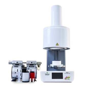
- Dental Porcelain Zirconia Sintering Ceramic Vacuum Press Furnace
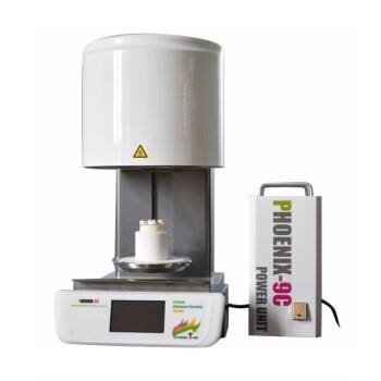
- Chairside Dental Porcelain Zirconia Sintering Furnace with Transformer for Ceramic Restorations
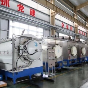
- High Temperature Muffle Oven Furnace for Laboratory Debinding and Pre Sintering
- Vacuum Dental Porcelain Sintering Furnace for Dental Laboratories
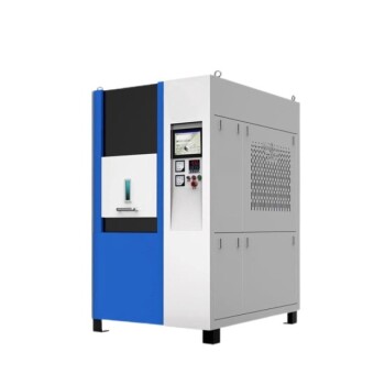
- Vacuum Heat Treat Sintering Furnace Molybdenum Wire Vacuum Sintering Furnace
People Also Ask
- What factors determine the quality of sintered zirconia restorations? Master Material, Equipment, and Technique
- How do conventional vs rapid sintering in dental furnaces affect zirconia? Optimize Efficiency Without Sacrificing Strength
- What is the purpose of dental sintering furnaces? Transform Zirconia into Durable, High-Quality Dental Restorations
- What precautions should be taken when sintering zirconia in the Fast Slow Dental Sintering Furnace? Master Key Steps for Perfect Results
- What temperature range is used for sintering zirconia ceramics? Achieve Optimal Strength and Translucency