Die-surface PID control in SPS systems creates thermal lag and oscillations because the heat isn't actually generated at the die surface—it's generated in the punches. When the sensor is far from the heat source, the PID loop reacts to delayed temperature readings, leading to current overshoots and unstable cycling. The solution is to relocate the control point closer to the true thermal driver, or physically reduce the distance heat must travel.
The root cause of regulation instability is a geometric mismatch between heat generation and temperature sensing. In conductive SPS assemblies, the punches are the primary Joule heating elements. Placing the PID sensor on the die surface introduces a significant thermal lag across a high-resistance interface, which causes the controller to overcorrect and oscillate. Moving the regulation point to the punches or shortening the punch height directly addresses this lag, enabling stable, precise control and more uniform sample heating.
The Thermal Dynamics of SPS Systems
To solve the oscillation problem, you must first understand where heat is actually born—and where it isn’t. The physics of current flow in conductive tooling shifts the thermal center away from where most sensors sit.
Where Heat is Really Generated: The Punch-Centric Reality
In high-temperature SPS configurations with conductive samples or thick dies, the primary Joule heating occurs in the punches. The electric current density is highest in these narrow, high-resistance pathways.
The die body, by contrast, often acts as a thermal sink and a physical constraint rather than a heater. This means the maximum thermal responsiveness is not at the die surface but at the mid-height of the punches. That’s the region where temperature changes fastest and most faithfully follows the applied power.
The Bottleneck: Thermal Contact Resistance at the Punch-Die Interface
Between the punch and the die lies a vertical interface with high thermal contact resistance (TCR). Even under high uniaxial pressure, microscopic gaps and surface asperities restrict heat flow.
This TCR acts like a thermal bottleneck. Heat generated in the punch must overcome this resistance before it can raise the die’s temperature. The die itself also possesses significant thermal mass, further slowing the response. The result is a physical time lag between when power is applied and when the die-surface sensor registers a temperature change.
Why Die-Surface PID Control Fails at High Temperatures
A PID controller is only as good as its feedback signal. When that signal is inherently delayed, the control loop becomes its own worst enemy.
The Time Lag Problem: Delayed Feedback Causes Overshoot
PID algorithms react to the error between the setpoint and the measured temperature. With the sensor on the die surface, that measurement is always a historical artifact. When the controller increases current to raise the die temperature, the heat must first build up in the punches.
The die surface remains "cold" long after the punches have reached extreme temperatures. The PID, seeing no immediate response, continues to ramp up current. By the time the die surface finally reaches the setpoint, the punches are already overheated, and excess thermal energy is already in transit.
The Oscillation Cycle: A Self-Perpetuating Instability
The inevitable consequence is a current overshoot. Once the die surface hits or exceeds the setpoint, the PID slams the current down. But that residual heat in the punches continues to flow into the die, causing a temperature spike above the target.
Then, as the system cools below the setpoint, the cycle repeats. This creates sustained oscillations in both temperature and current. The control precision degrades, and the sample experiences a fluctuating thermal environment that undermines process repeatability.
Understanding the Trade-Offs
Shifting away from die-surface control is not a matter of simply moving a wire. It requires rethinking the control architecture and accepting a different set of operational constraints.
The primary trade-off is informational: The die surface is often the closest accessible proxy for the sample temperature. Moving the sensor to the punch mid-height means you are now controlling the heat source, not the load. You must have strong confidence in the thermal model linking punch temperature to sample temperature. If that relationship is not well-characterized, you risk misinterpreting the actual sample conditions.
A secondary consideration is sensor durability and installation. Placing a thermocouple or pyrometer at the punch mid-height requires careful mechanical integration, especially under high loads. However, for applications demanding tight temperature tolerances, this effort is almost always justified.
How to Apply This to Your SPS Process
The solution centers on minimizing the thermal lag between heat generation and the measurement point. Two practical engineering interventions—often used together—can dramatically improve control precision.
Repositioning the PID Regulation Point to the Punches
The most direct fix is to move the control thermocouple or pyrometer from the die surface to the mid-height of the punches. This places the sensor exactly where the thermal responsiveness is highest.
With feedback now in sync with the heat source, the PID loop sees temperature changes in near-real time. Current overshoots are dampened, and the system settles into a stable power delivery pattern. This change alone can eliminate the oscillatory behavior and enable high-temperature operation with tight tolerances.
Reducing Punch Height to Minimize Thermal Lag
If sensor relocation is not feasible, an alternative is to shorten the punch height. Reducing the physical distance between the primary heating zone and the die surface lowers the thermal mass and resistance that heat must traverse.
Shorter punches mean the die surface reaches temperature with less delay. The time lag shrinks, bringing the sensor’s feedback signal closer to the real thermal state of the system. This dampens oscillations and, as a secondary benefit, promotes more homogeneous heat distribution through the entire assembly.
Achieving More Homogeneous Sample Heating
The ultimate goal is not just stable control, but a uniform thermal field across the sample. Both strategies—punch-based control and reduced punch height—work toward this. By aligning the regulation point with the true thermal driver, you prevent the extreme thermal gradients that cause sample inhomogeneity.
Because the system no longer overshoots and then crashes, the axial temperature profile through the sample becomes more even. This is critical for sintering defect-free, high-performance materials where even small gradients can cause density variations or phase segregation.
Making the Right Choice for Your Goal
Your approach depends on your specific priorities and hardware flexibility.
- If your primary focus is eliminating oscillations immediately: Move the PID control sensor to the mid-height of the punches. This provides the most direct feedback and the fastest stabilization.
- If your primary focus is minimizing hardware modifications: Reduce the punch height to shrink the thermal lag while maintaining a die-surface sensor, though you may still need to re-tune the PID gains.
- If your primary focus is maximizing sample uniformity: Combine both strategies—reposition the sensor and shorten the punches—to dampen oscillations and reduce axial gradients simultaneously.
The core principle is timeless: a controller can only regulate what it can truly see. Closing the physical gap between the heat source and the sensor turns a chaotic thermal loop into a predictable, precise process.
Summary Table:
| Challenge / Strategy | Cause & Mechanism | Engineering Solution & Benefit |
|---|---|---|
| Thermal Lag & Overshoot | Primary heat is generated in punches; high thermal contact resistance at die interface delays feedback | Reposition Sensor to Punches: Places feedback at the heat source to eliminate delayed readings and prevent overshooting. |
| Current Oscillations | PID loop overcorrects due to delayed response, triggering repeating temperature spikes and dips | Reduce Punch Height: Minimizes distance and thermal resistance between source and sensor, dampening oscillations. |
| Sample Inhomogeneity | Extreme thermal gradients from fluctuating current cause density variations and defects | Combine Both Approaches: Stabilizes thermal field and delivers uniform axial heat distribution for defect-free samples. |
Achieve exceptional thermal stability and process repeatability in your laboratory with KINTEK. Specializing in high-performance laboratory equipment and consumables, KINTEK delivers a comprehensive range of high-temperature furnaces—including muffle, tube, rotary, vacuum, CVD, atmosphere, dental, and induction melting systems—all fully customizable to solve your toughest thermal processing challenges. Boost your control precision and material performance today—contact KINTEK experts now!
Related Products
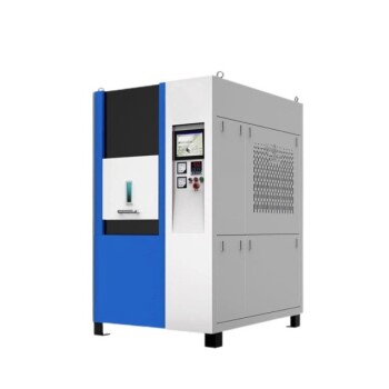
- Spark Plasma Sintering SPS Furnace
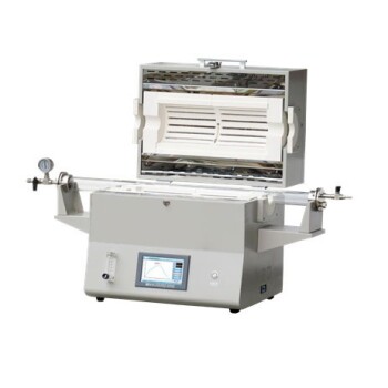
- 1400℃ High Temperature Laboratory Tube Furnace with Alumina Tube
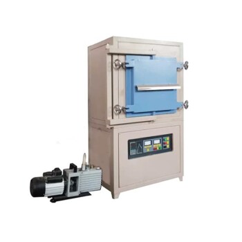
- 1700℃ Controlled Inert Nitrogen Atmosphere Furnace
- 1200℃ Split Tube Furnace Laboratory Quartz Tube Furnace with Quartz Tube
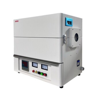
- 1700℃ High Temperature Laboratory Tube Furnace with Alumina Tube
People Also Ask
- Why is it necessary to maintain a high vacuum environment during the SPS of SiC? Key to High-Density Ceramics
- How does the heating mechanism of Spark Plasma Sintering (SPS) function? Enhance TiC/SiC Composite Fabrication
- What are the technical advantages of using an SPS sintering furnace? Elevate Al2O3-TiC Material Performance
- What are the advantages of Spark Plasma Sintering (SPS)? Achieve Superior Microstructures
- What are the steps in the discharge plasma sintering process? Master Fast, High-Density Material Consolidation