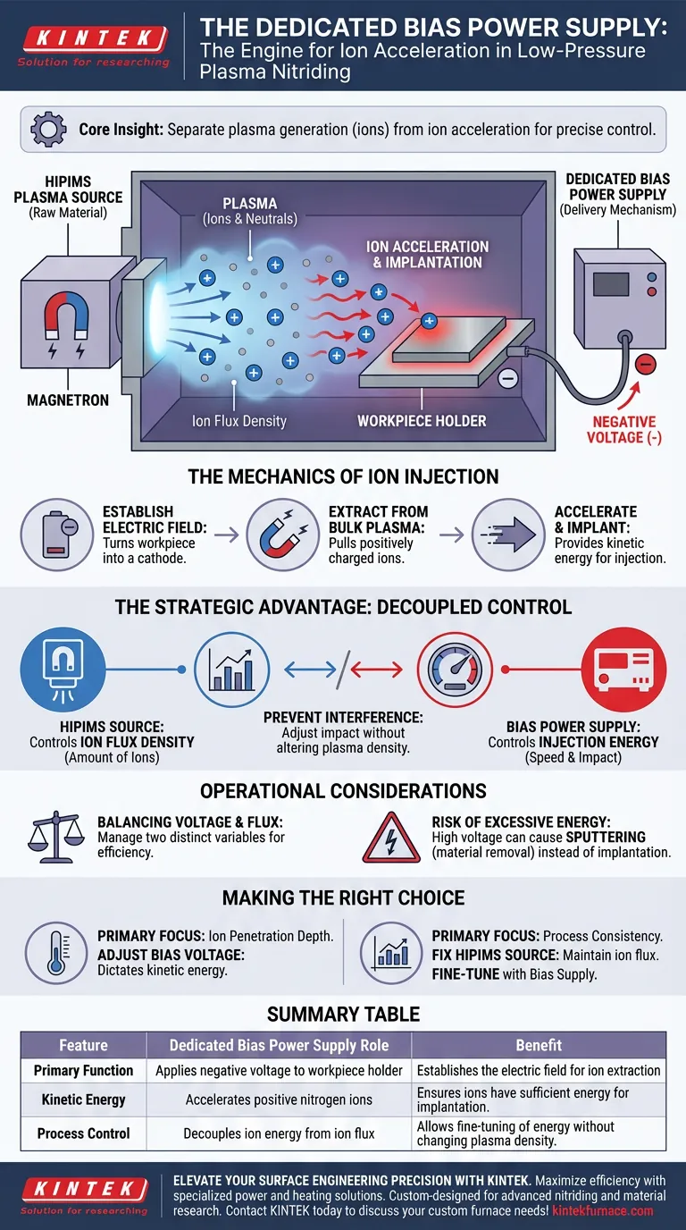
A dedicated bias power supply acts as the primary engine for ion acceleration. Its specific role is to apply a negative voltage to the workpiece holder, establishing an electric field that extracts nitrogen ions from the bulk plasma. By accelerating these ions, the power supply ensures they impact the workpiece surface with the necessary kinetic energy for successful implantation.
Core Insight: While the plasma source generates the raw material (ions), the bias power supply controls the delivery mechanism. This separation allows you to adjust how hard the ions hit the surface without unintentionally altering the density of the plasma cloud.
The Mechanics of Ion Injection
To understand the necessity of a dedicated bias supply, one must look at how it interacts with the plasma environment created by the source (typically a High Power Impulse Magnetron Sputtering, or HIPIMS, source).
Establishing the Electric Field
The bias power supply connects directly to the workpiece holder. By applying a negative voltage, it turns the workpiece itself into a cathode relative to the plasma.
Extraction from Bulk Plasma
This negative potential creates a strong electric field. This field effectively extracts positively charged ions from the bulk plasma cloud that is hovering around the workpiece.
Acceleration and Implantation
Once extracted, the ions are accelerated toward the surface. The bias supply creates the velocity required to inject these ions into the material lattice, driving the actual nitriding process.
The Strategic Advantage: Decoupled Control
The most significant technical advantage of using a dedicated bias power supply is the ability to separate plasma generation from ion acceleration.
Separating Roles
In this setup, the HIPIMS source is solely responsible for generating the plasma and determining the ion flux density (the amount of ions available).
Independent Energy Regulation
Meanwhile, the bias power supply takes over the control of injection energy (the speed and impact force of the ions).
Preventing Process Interference
Because these functions are separated, you can increase or decrease the impact energy without changing the number of ions present. This decoupled control allows for precise fine-tuning of the material properties that is not possible when generation and acceleration are tied to a single source.
Operational Considerations
While decoupling offers superior control, it requires a clear understanding of the relationship between your power sources.
Balancing Voltage and Flux
You must manage two distinct variables: the density provided by the HIPIMS source and the voltage provided by the bias supply. Misalignment here can lead to inefficient processing.
The Risk of Excessive Energy
If the bias voltage is set too high relative to the process requirements, you risk transitioning from implantation (nitriding) to sputtering (removing material). Precise control of the bias supply is required to maintain the correct energy window.
Making the Right Choice for Your Process
Optimizing your nitriding process requires distinct strategies for your power supply settings.
- If your primary focus is Ion Penetration Depth: Focus on adjusting the bias voltage, as this directly dictates the kinetic energy and subsequent implantation depth of the ions.
- If your primary focus is Process Consistency: Maintain a stable setting on your HIPIMS source to fix the ion flux, using the bias supply only to fine-tune the surface interaction.
A dedicated bias power supply transforms nitriding from a passive exposure process into an active, controllable injection technique.
Summary Table:
| Feature | Dedicated Bias Power Supply Role | Benefit |
|---|---|---|
| Primary Function | Applies negative voltage to workpiece holder | Establishes the electric field for ion extraction |
| Kinetic Energy | Accelerates positive nitrogen ions | Ensures ions have sufficient energy for implantation |
| Process Control | Decouples ion energy from ion flux | Allows fine-tuning of energy without changing plasma density |
| Operational Goal | Regulates injection energy | Prevents material sputtering while maximizing penetration depth |
Elevate Your Surface Engineering Precision with KINTEK
Maximize the efficiency of your plasma processes with specialized power and heating solutions. Backed by expert R&D and manufacturing, KINTEK offers high-performance Muffle, Tube, Rotary, Vacuum, and CVD systems—all fully customizable to meet the rigorous demands of advanced nitriding and material research.
Whether you need to optimize ion penetration depth or ensure process consistency, our technical experts are ready to design the perfect high-temperature setup for your lab.
Ready to refine your thermal processing? Contact KINTEK today to discuss your custom furnace needs!
Visual Guide
References
- Arutiun P. Ehiasarian, P.Eh. Hovsepian. Novel high-efficiency plasma nitriding process utilizing a high power impulse magnetron sputtering discharge. DOI: 10.1116/6.0003277
This article is also based on technical information from Kintek Furnace Knowledge Base .
Related Products
People Also Ask
- What are the main types of sintering furnaces? Find the Perfect Match for Your Materials
- What is unique about the heating mechanism of a Spark Plasma Sintering (SPS) furnace when preparing nanostructured h-BN ceramics? Achieve Ultra-Fast Densification and Suppress Grain Growth
- What are the steps in the discharge plasma sintering process? Master Fast, High-Density Material Consolidation
- What is the significance of high-precision temperature monitoring systems in SPS? Control Ti-6Al-4V/HA Microstructure
- Why is it necessary to maintain a high vacuum environment during the SPS of SiC? Key to High-Density Ceramics