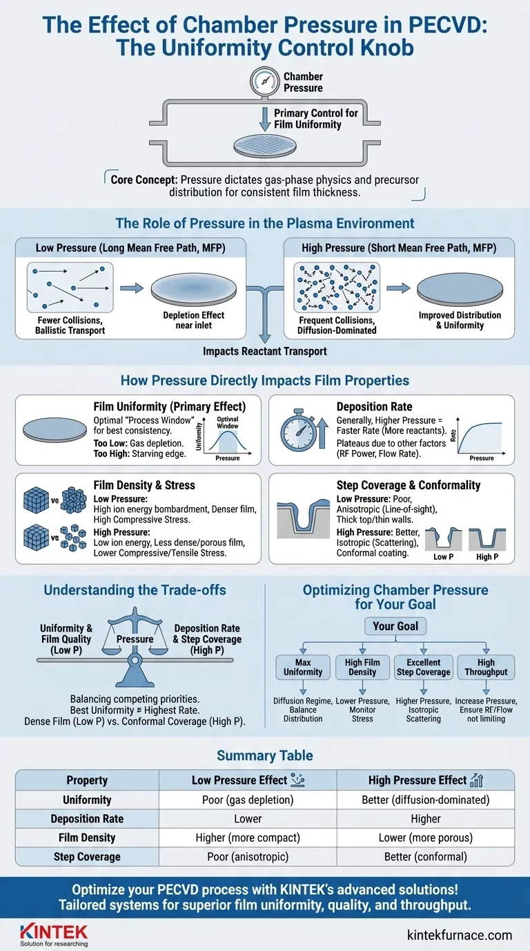
At its core, chamber pressure in a Plasma-Enhanced Chemical Vapor Deposition (PECVD) system is the primary control knob for film uniformity. By adjusting the pressure, you directly manipulate the gas-phase physics within the chamber, which in turn dictates how evenly the deposition precursors are distributed across the substrate surface. Finding the optimal pressure is key to achieving consistent film thickness from the center of the wafer to its edge.
The central challenge is that chamber pressure does not act in isolation. It creates a series of trade-offs between film uniformity, deposition rate, film quality, and step coverage. Mastering PECVD requires understanding how to balance these competing factors by selecting the right pressure for your specific goal.
The Role of Pressure in the Plasma Environment
To understand how pressure affects the final film, you must first understand how it changes the conditions within the plasma itself. The entire process hinges on the behavior of gas molecules and ions.
Mean Free Path and Collisions
Mean free path (MFP) is the average distance a gas particle travels before colliding with another. This is the single most important concept governed by pressure.
At low pressure, the chamber has fewer gas molecules. This results in a long mean free path, meaning particles can travel further without colliding.
At high pressure, the chamber is crowded with gas molecules. This leads to a short mean free path and frequent collisions between particles.
Reactant Transport and Distribution
Pressure determines how the reactant gases (precursors) get from the gas inlet to the wafer surface.
At low pressures, transport is "ballistic" or convection-dominated. Gas molecules move in relatively straight lines. This can lead to a depletion effect, where the area near the gas inlet gets a thicker coating than areas further away.
At high pressures, the short mean free path means transport becomes diffusion-dominated. Reactants scatter in all directions, which can average out their distribution and improve uniformity across the wafer.
How Pressure Directly Impacts Film Properties
The changes in the plasma environment have direct, predictable consequences on the characteristics of the deposited film.
Film Uniformity (The Primary Effect)
As stated, this is the main reason for optimizing pressure. There is typically an optimal "process window" for pressure that yields the best uniformity.
Operating at too low a pressure can cause non-uniformity due to gas depletion. Operating at too high a pressure can cause non-uniformity due to residence time effects or "starving" the wafer edge of reactants.
Deposition Rate
Generally, a higher pressure increases the deposition rate. This is because there are simply more reactant molecules available in the chamber to participate in the film-forming reactions.
However, this effect plateaus. At a certain point, the rate will become limited by other factors, such as RF power (the energy to break down precursors) or the precursor flow rate.
Film Density and Stress
Pressure strongly influences the energy of ions bombarding the substrate, which affects film density.
At low pressure, the long mean free path allows ions to accelerate and strike the surface with high energy. This bombardment creates a denser, more compact film, often with high compressive stress.
At high pressure, frequent collisions cause ions to lose energy before they reach the surface. The resulting low-energy deposition produces a less dense, more porous film with lower compressive or even tensile stress.
Step Coverage and Conformality
Step coverage describes how well a film covers the topography of a patterned wafer, such as trenches or vias.
Low pressure and its associated high-energy, directional ion flux lead to poor step coverage. The deposition is highly anisotropic, or "line-of-sight," resulting in thick film on top surfaces and very thin film on sidewalls.
High pressure promotes gas-phase scattering, making the arrival of film precursors more isotropic (coming from all angles). This significantly improves step coverage and produces a more conformal coating.
Understanding the Trade-offs
Optimizing chamber pressure is rarely about maximizing a single parameter. It is an exercise in managing competing priorities.
Uniformity vs. Rate
The pressure that provides the absolute best uniformity is often not the pressure that gives the highest deposition rate. A process engineer must balance the need for throughput (rate) with the specification for film consistency (uniformity).
Film Quality vs. Step Coverage
A dense, hard film (achieved at low pressure) is often desirable for its protective properties. However, those same low-pressure conditions yield poor step coverage. Conversely, the high-pressure conditions needed for excellent conformality can produce a lower-quality, less dense film.
The Complete Process Window
Pressure cannot be set in a vacuum. Its effects are deeply intertwined with RF power, gas flow rates, substrate temperature, and chamber geometry. A change in pressure often requires a corresponding adjustment in other parameters to keep the process centered in its optimal window.
Optimizing Chamber Pressure for Your Goal
Your choice of pressure should be dictated by the primary requirement of your deposited film.
- If your primary focus is maximum within-wafer uniformity: Operate within the diffusion-limited pressure regime, carefully balancing reactant distribution without starving the wafer edge.
- If your primary focus is high film density and low etch rate: Use a lower pressure to increase ion energy and bombardment, but monitor film stress to prevent cracking or delamination.
- If your primary focus is excellent step coverage on 3D structures: Use a higher pressure to increase gas-phase scattering for a more conformal coating.
- If your primary focus is high throughput (deposition rate): Increase pressure to provide more reactants, but ensure you are not limited by RF power or precursor flow.
Ultimately, chamber pressure is one of the most powerful levers for controlling your film's final properties, requiring a deliberate balance to achieve your specific engineering goal.
Summary Table:
| Property | Low Pressure Effect | High Pressure Effect |
|---|---|---|
| Uniformity | Poor (gas depletion) | Better (diffusion-dominated) |
| Deposition Rate | Lower | Higher |
| Film Density | Higher (more compact) | Lower (more porous) |
| Step Coverage | Poor (anisotropic) | Better (conformal) |
Optimize your PECVD process with KINTEK's advanced solutions! Leveraging exceptional R&D and in-house manufacturing, we provide diverse laboratories with high-temperature furnace systems, including CVD/PECVD Systems, tailored to your unique needs. Our deep customization capability ensures precise control over chamber pressure and other parameters for superior film uniformity, quality, and throughput. Contact us today to discuss how we can enhance your experimental outcomes and drive innovation in your lab!
Visual Guide
Related Products
- Slide PECVD Tube Furnace with Liquid Gasifier PECVD Machine
- Inclined Rotary Plasma Enhanced Chemical Deposition PECVD Tube Furnace Machine
- RF PECVD System Radio Frequency Plasma Enhanced Chemical Vapor Deposition
- Inclined Rotary Plasma Enhanced Chemical Deposition PECVD Tube Furnace Machine
- Split Chamber CVD Tube Furnace with Vacuum Station CVD Machine
People Also Ask
- What are the advantages of using a tube furnace CVD system for Cu(111)/graphene? Superior Scalability and Quality
- In which industries is the tube furnace commonly used? Essential for Materials Science, Energy, and More
- What plasma source is used in PE-CVD tube furnaces? Unlock Low-Temperature, High-Quality Deposition
- What are the disadvantages of tube furnace cracking when processing heavy raw materials? Avoid Costly Downtime and Inefficiency
- What is plasma in the context of PECVD? Unlock Low-Temperature Thin Film Deposition