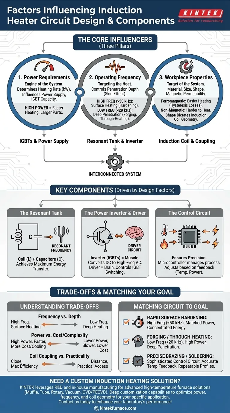
At its core, an induction heater circuit's design is a direct response to three primary factors: the required power, the operating frequency, and the physical and magnetic properties of the material you intend to heat. These variables are not independent; they form an interconnected system where a decision about one directly impacts the requirements for the others, dictating every component choice from the power supply to the shape of the induction coil itself.
The central challenge in induction heater design is not just generating heat, but efficiently matching the circuit's electromagnetic field to the specific workpiece. Every component is chosen to achieve this resonance, ensuring that electrical energy is effectively converted into thermal energy precisely where it is needed.
The Three Pillars of Induction Heater Design
The entire circuit is an engineered solution to a specific heating problem. Understanding the three foundational requirements clarifies why certain components and topologies are chosen.
Power Requirements: The Engine of the System
The power output, measured in kilowatts (kW), determines the rate at which you can deliver energy to the workpiece. This is dictated by the mass of the part, the desired temperature rise, and the time you have to achieve it.
A larger workpiece or a faster heating requirement demands higher power. This decision directly influences the selection of the main power supply and the current-handling capacity of the switching components, such as IGBTs (Insulated-Gate Bipolar Transistors).
Operating Frequency: Targeting the Heat
Frequency is perhaps the most critical design parameter. It controls the depth to which the induced currents penetrate the workpiece, a phenomenon known as the skin effect.
High frequencies (e.g., 50 kHz to 400 kHz) confine the heating to the surface of the material. This is ideal for applications like surface hardening, where you need a hard outer case and a ductile core.
Low frequencies (e.g., 1 kHz to 20 kHz) penetrate much deeper into the material. This is necessary for applications like forging or through-heating, where the entire bulk of the workpiece must reach a uniform temperature.
Workpiece Properties: The Target of the System
The circuit must be tailored to the material being heated. The key properties are its size, shape, and magnetic permeability.
Ferromagnetic materials like iron and steel are much easier to heat than non-magnetic materials like copper or aluminum. This is because they benefit from hysteresis losses in addition to the standard eddy current heating, making the process more efficient at lower frequencies.
The shape of the workpiece dictates the geometry of the induction coil. The coil must be designed to "couple" effectively with the part, ensuring the magnetic field is concentrated in the target heating zone for maximum energy transfer.
Key Components Driven by Design Factors
The three pillars of design directly inform the selection and specification of the circuit's core components.
The Resonant Tank: Coil and Capacitors
The heart of the heater is the resonant tank circuit, typically consisting of the work coil (an inductor, L) and a bank of capacitors (C). The values of L and C are chosen to create a specific resonant frequency.
The system is designed to operate at or near this frequency because it allows for the maximum transfer of energy from the power supply to the coil, creating a powerful oscillating magnetic field with minimal electrical stress on the switching components.
The Power Inverter and Driver Circuit
The inverter, often built with IGBTs, is the muscle of the circuit. It takes DC from the power supply and chops it into a high-frequency AC waveform. The driver circuit is the brain that tells the IGBTs precisely when to switch on and off.
The power and frequency requirements determine the voltage and current ratings of these IGBTs and the sophistication of the driver circuit needed to control them accurately.
The Control Circuit: Ensuring Precision
A modern induction heater relies on a control circuit, often a microcontroller, to manage the entire process. This circuit monitors feedback from sensors (like thermocouples for temperature or current sensors for power).
Based on this feedback, it adjusts the driver circuit's output. This allows for precise regulation of power, frequency, and temperature, enabling repeatable and automated heating cycles for applications like brazing or heat treating.
Understanding the Trade-offs
Designing an induction circuit is an exercise in balancing competing factors. There is no single "best" design, only the optimal design for a specific task.
Frequency vs. Heating Depth
Choosing a high frequency gives you precise surface heating but will fail to heat the core of a large part. Conversely, a low frequency will provide deep, penetrating heat but is inefficient for treating only the surface.
Power vs. Cost and Complexity
Increasing the power output allows for faster heating but comes at a significant cost. High-power IGBTs, larger capacitors, and more robust cooling systems (water cooling is common) dramatically increase the price and complexity of the system. Over-specifying power is a common and expensive mistake.
Coil Coupling vs. Practicality
For maximum efficiency, the induction coil should be as close to the workpiece as possible. However, in an industrial setting, you may need clearance for robotic loading/unloading or to accommodate irregular part shapes. This forces a compromise, trading some efficiency for practicality.
Matching Your Circuit to Your Goal
Your application's primary goal should be the ultimate guide for your design choices.
- If your primary focus is rapid surface hardening: Prioritize a high-frequency design (>50 kHz) with a power level matched to the surface area to concentrate energy exactly where it's needed.
- If your primary focus is forging or through-heating thick materials: Choose a lower-frequency (<20 kHz) and high-power design to ensure the heat can fully penetrate to the core of the workpiece.
- If your primary focus is precise, repeatable processes like brazing or soldering: Invest in a sophisticated control circuit with accurate temperature feedback, allowing you to execute precise heating profiles.
A successful induction heater design is a deliberate alignment of power, frequency, and coil geometry to serve a specific heating application.
Summary Table:
| Factor | Influence on Circuit Design | Key Components Affected |
|---|---|---|
| Power Requirements | Determines heating rate and energy delivery | Power supply, IGBTs, cooling systems |
| Operating Frequency | Controls heating depth via skin effect | Resonant tank (coil and capacitors), inverter |
| Workpiece Properties | Affects efficiency and coil coupling | Induction coil geometry, material selection |
Need a custom induction heating solution? At KINTEK, we leverage exceptional R&D and in-house manufacturing to provide advanced high-temperature furnace solutions tailored to your unique needs. Our product line includes Muffle, Tube, Rotary Furnaces, Vacuum & Atmosphere Furnaces, and CVD/PECVD Systems, all supported by strong deep customization capabilities. Whether you're in surface hardening, forging, or precise brazing, we can design a system that optimizes power, frequency, and coil geometry for maximum efficiency. Contact us today to discuss how we can enhance your laboratory's performance!
Visual Guide
Related Products
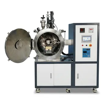
- 600T Vacuum Induction Hot Press Vacuum Heat Treat and Sintering Furnace
- Vacuum Induction Melting Furnace
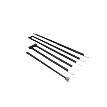
- Silicon Carbide SiC Thermal Heating Elements for Electric Furnace
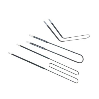
- Molybdenum Disilicide MoSi2 Thermal Heating Elements for Electric Furnace
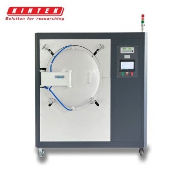
- Vacuum Heat Treat Furnace with Ceramic Fiber Liner
People Also Ask
- How are vacuum hot pressing sintering furnaces classified based on temperature? Explore Low, Medium, and High-Tier Solutions
- Why use Vacuum Hot Press (VHP) for ZnS Ceramics? Achieve Superior IR Transparency and Mechanical Strength
- What is the core function of a vacuum hot press sintering furnace in the preparation of high-density RuTi alloys? Achieve Maximum Density and Purity
- What are the different types of heating methods in vacuum hot press sintering furnaces? Compare Resistance vs. Induction
- How does the vacuum environment in a vacuum hot press sintering furnace protect chromium-containing ceramics? Find out.