The core trade-off is between process simplicity and final fiber quality. Drawing from a monolithic sol-gel preform gives you a cleaner, more consolidated starting state that avoids crucible contamination and reduces porosity, but it demands long processing times and often yields poorer optical quality. Drawing directly from a viscous sol at room temperature is a lower-temperature route to highly refractory, durable fibers, yet it forces you to manage the complexities of microporosity, organic burnout, and cross-sectional uniformity during subsequent sintering.
Both methods bypass traditional melt processing and crucible contamination, but they diverge sharply in when and how the solid-to-fiber transformation occurs. The monolithic preform approach shifts the densification effort to an earlier stage, while direct sol-drawing postpones densification until after fiber formation, trading early simplicity for later thermal management challenges.
The Monolithic Sol-Gel Preform Route: How It Works
This method creates a solid, partially dense cylinder (preform) via sol-gel chemistry, then heats it above its softening temperature and draws a continuous fiber.
Contamination Avoidance and Cleanliness
No crucible touches the molten or softened material during drawing. Because the preform is synthesized entirely through a wet-chemical route, it eliminates the crucible-induced impurities common in conventional melt-drawing.
The Price of a Solid Starting Point
Producing a crack-free, optically homogeneous preform is slow. The sol-to-gel transition, aging, drying, and subsequent partial sintering can take days or weeks, making processing time a major drawback.
Optical Quality Limitation
This route historically struggles to match the transparency and low-attenuation of fibers drawn from chemical-vapor-deposited preforms. If your application demands photonic-grade clarity, this method often falls short.
The Direct Viscous Sol Drawing Route: How It Works
Here, you draw fibers directly from a concentrated sol at ambient temperature, forming a green fiber that is later densified by sintering.
Low Thermal Budget for Refractory Compositions
The sol can be drawn at room temperature, and the final sintering step requires far less energy than melt processing. This makes it feasible to create extremely refractory, chemically durable fibers (like SiO₂–Al₂O₃ or SiO₂–ZrO₂) without reaching their melting points.
The Three Critical Challenges
Three interlinked problems define the trade-offs for this technique.
Microporosity Management
The green fiber is a gel network filled with solvent. Upon drying and sintering, a huge volume reduction occurs, leaving behind fine-scale microporosity that can act as flaws and reduce mechanical strength if not perfectly closed.
Removal of Residual Organics
Organic precursors or additives used to tune the sol’s rheology must be completely burned out. This thermal debinding step is a delicate balancing act: heat too fast, and gas evolution creates bubbles or cracks; heat too slow, and productivity plummets.
Cross-Sectional Non-Uniformity
Liquids extrude smoothly, but drying and sintering can distort the fiber’s shape. Shrinkage is rarely perfectly isotropic, often leading to slight ovality or surface undulations that demand tight process control.
Understanding the Trade-Offs in Tandem
Putting the two side by side reveals a classic processing science dilemma: pre-fiber densification versus post-fiber densification.
Densification Timing
The monolithic preform method accomplishes much of the densification before fiber drawing. The preform itself is already partly consolidated. This reduces the burden of shrinkage during drawing, leading to more dimensionally stable fibers with potentially fewer internal flaws from later densification.
In contrast, direct sol drawing defers nearly all volumetric shrinkage to the sintering stage. While this allows much simpler ambient-temperature fiber forming, it concentrates the risk of defect formation into a single, sensitive thermal treatment.
Compositional Flexibility vs. Speed
Direct sol drawing excels in producing chemically durable, multi-component oxides that would be impossible or impractical to melt. You can tailor the chemical composition easily by mixing precursors in the sol.
The preform route, although time-consuming, can yield a more consistent product once the preform is perfected, but tweaking compositions requires starting the lengthy preform synthesis from scratch.
Typical Use-Case Implications
If you need a low-defect, dense ceramic fiber for structural reinforcement and can tolerate a long lead time, the monolithic preform route is attractive. If your goal is a highly refractory, chemically durable fiber for filtration or catalyst supports where some porosity is acceptable or even desired, direct sol drawing is more practical.
Making the Right Choice for Your Goal
Your decision hinges on whether you can accept the densification challenges after fiber formation in exchange for a simpler drawing step, or whether you’d rather invest heavily upfront to get a cleaner, more consolidated starting material.
- If your primary focus is maximum structural integrity with minimal internal porosity: The monolithic sol-gel preform route is the stronger candidate, provided you can manage the long processing time and accept optical quality limitations.
- If your primary focus is creating a chemically durable, refractory fiber with a simpler, low-temperature forming step: Direct viscous-sol drawing wins, but you must master the debinding and sintering process to control microporosity and shape.
Every ceramic fiber process shapes the material’s destiny long before the final application. Choose the path that aligns your tolerance for process time with your tolerance for post-form densification risk.
Summary Table:
| Feature / Trade-off | Monolithic Sol-Gel Preform Route | Direct Viscous Sol Drawing Route |
|---|---|---|
| Densification Stage | Pre-fiber drawing (during preform stage) | Post-fiber forming (during sintering) |
| Thermal Budget & Cost | Higher energy requirement for preform | Low-temperature drawing; lower energy budget |
| Processing Lead Time | Long (days/weeks for drying & pre-sintering) | Short (direct room-temperature extrusion) |
| Key Quality Risks | Poor optical clarity, long lead times | Microporosity, organic residue, shape distortion |
| Best For Applications | High-strength structural reinforcement | Highly refractory, chemically durable filters/supports |
Mastering thermal debinding and precise sintering is critical to producing defect-free ceramic fibers. KINTEK provides industry-leading laboratory equipment and custom high-temperature furnaces—including muffle, tube, atmosphere, CVD, and vacuum furnaces—tailored to your exact sol-gel processing needs. Enhance your lab's material synthesis and heat-treatment accuracy today: Contact KINTEK for custom furnace solutions!
Related Products
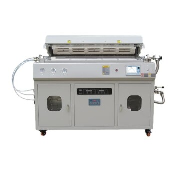
- High Temperature Muffle Oven Furnace for Laboratory Debinding and Pre Sintering
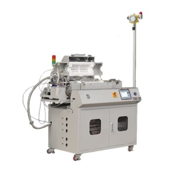
- Multi Heating Zones CVD Tube Furnace Machine for Chemical Vapor Deposition Equipment
- Vacuum Dental Porcelain Sintering Furnace for Dental Laboratories
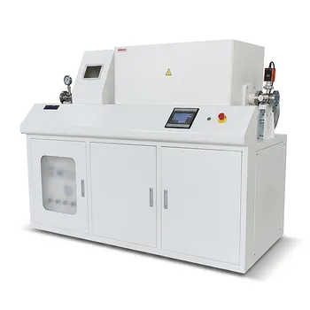
- Custom Made Versatile CVD Tube Furnace Chemical Vapor Deposition CVD Equipment Machine
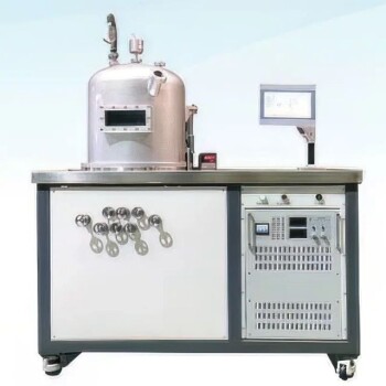
- HFCVD Machine System Equipment for Drawing Die Nano Diamond Coating
People Also Ask
- What thermal phenomena occur during polymer binder burnout in ceramic green bodies? Lab Furnace Guide
- What role does a high-temperature muffle furnace play in STFO synthesis? Achieve Pure Perovskite Results
- Why is controlled heat treatment in a muffle furnace necessary for calcined clay? Achieve Optimal Pozzolanic Activity
- How does a high-temperature muffle furnace facilitate the formation of LaNbxAl1−xO3+δ perovskite structures? Key Roles
- What role does a high-temperature muffle furnace play in the formation of biochar catalysts? Master Catalyst Synthesis