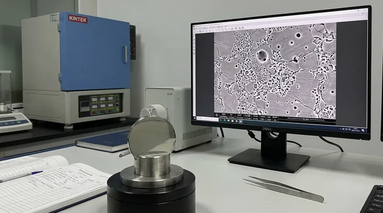
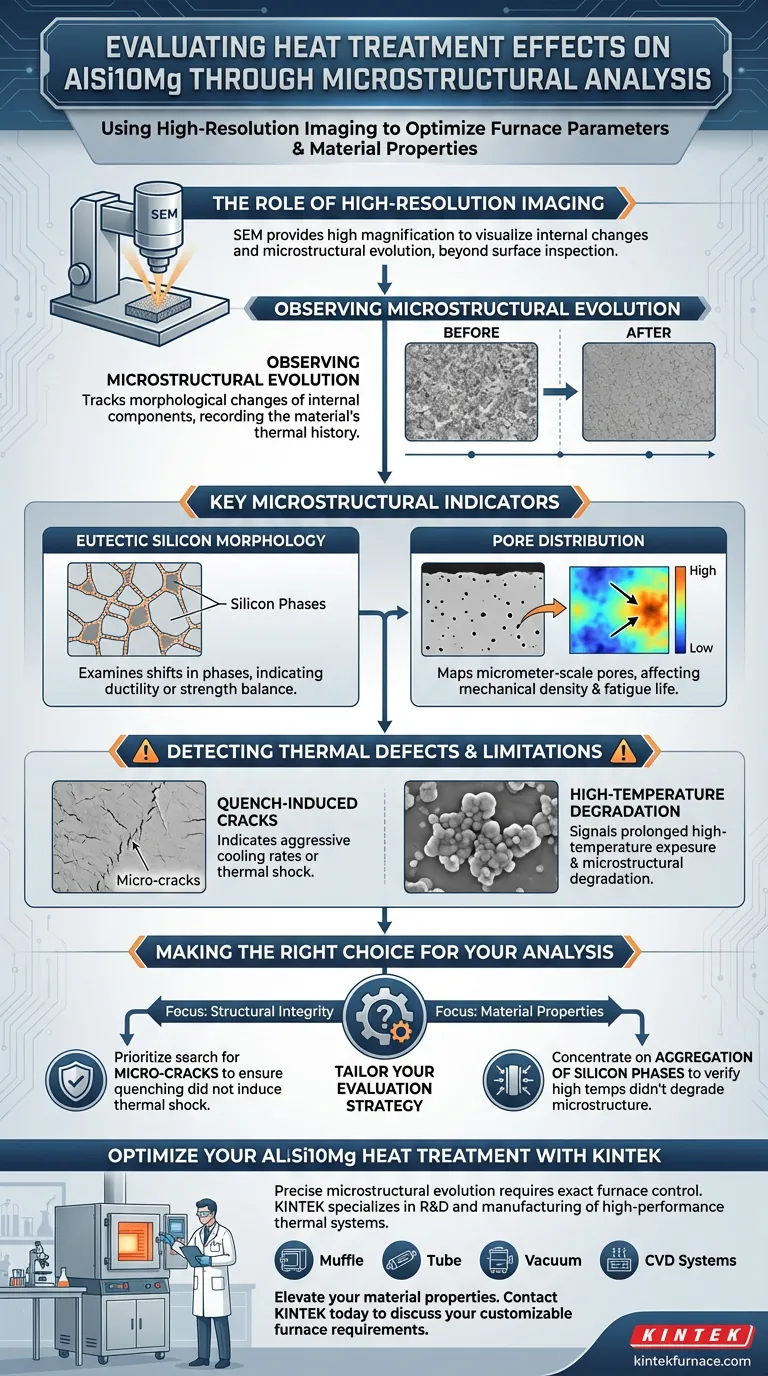
The evaluation of heat treatment effectiveness relies on high-resolution imaging techniques. Specifically, Scanning Electron Microscopy (SEM) is utilized to visualize the internal changes within AlSi10Mg. This method allows for a detailed assessment of how furnace parameters influence eutectic silicon morphology and the distribution of micrometer-scale pores.
Visual evidence determines process quality. Analyzing microstructural evolution is essential to confirm that heat treatment settings optimize material properties rather than inducing thermal shock or degradation.
The Role of High-Resolution Imaging
Leveraging Scanning Electron Microscopy (SEM)
To accurately gauge the impact of furnace parameters, engineers must look beyond surface-level inspection. SEM provides the high magnification necessary to observe the evolution of the material's microstructure. This level of detail is required to capture subtle changes that indicate whether the treatment was successful.
Observing Microstructural Evolution
The primary focus of this analysis is observing how the material changes over time under heat. By comparing images before and after treatment, analysts track the morphological changes of the alloy's internal components. This evolution serves as a direct record of the thermal history the part has experienced.
Key Microstructural Indicators
Monitoring Eutectic Silicon Morphology
One of the most critical indicators of heat treatment effects is the state of the silicon within the alloy. Analysts examine the eutectic silicon morphology to understand how the phases have shifted. Changes here can indicate whether the material has achieved the desired ductility or strength balance.
Analyzing Pore Distribution
Heat treatment can alter the internal void structure of the material. Evaluations must map the distribution of micrometer-scale pores throughout the sample. A shift in pore distribution can affect the mechanical density and fatigue life of the component.
Detecting Thermal Defects and Limitations
Identifying Quench-Induced Cracks
A critical trade-off in heat treatment is the risk of thermal shock during rapid cooling. Microstructural analysis specifically looks for micro-cracks caused by quenching. The presence of these cracks indicates that the cooling rate was too aggressive for the material's geometry.
Recognizing High-Temperature Degradation
Excessive heat exposure can be just as damaging as rapid cooling. Analysts look for the aggregation of silicon phases, which occurs due to prolonged high-temperature exposure. This aggregation acts as visual evidence of microstructural degradation, signaling that the furnace parameters may have exceeded the optimal thermal window.
Making the Right Choice for Your Analysis
To ensure the reliability of your AlSi10Mg components, you must tailor your evaluation strategy to the specific risks of your heat treatment cycle.
- If your primary focus is Structural Integrity: Prioritize the search for micro-cracks to ensure the quenching process did not induce thermal shock.
- If your primary focus is Material Properties: Concentrate on the aggregation of silicon phases to verify that high temperatures have not degraded the microstructure.
Ultimately, the goal is to use visual data to validate that furnace settings improve the material without compromising its internal architecture.
Summary Table:
| Evaluation Indicator | Analysis Technique | Impact of Furnace Parameters |
|---|---|---|
| Eutectic Silicon Morphology | SEM Imaging | Determines material ductility and strength balance |
| Pore Distribution | Micrometer-scale Mapping | Affects mechanical density and component fatigue life |
| Quench-Induced Cracks | High-Resolution Inspection | Indicates excessive cooling rates or thermal shock |
| Phase Aggregation | Microstructural Comparison | Signals degradation due to prolonged high-temperature exposure |
Optimize Your AlSi10Mg Heat Treatment with KINTEK
Precise microstructural evolution requires exact furnace control. At KINTEK, we specialize in the R&D and manufacturing of high-performance thermal systems designed for the rigorous demands of advanced metallurgy.
Whether you need Muffle, Tube, Vacuum, or CVD systems, our laboratory high-temperature furnaces provide the thermal stability necessary to prevent phase aggregation and quenching defects.
Ready to elevate your material properties? Contact KINTEK today to discuss your customizable furnace requirements.
Visual Guide
References
- Busisiwe J. Mfusi, Ntombi Mathe. Optimisation of the Heat Treatment Profile for Powder-Bed Fusion Built AlSi10Mg by Age Hardening and Ice-Water Quenching. DOI: 10.3390/met14030292
This article is also based on technical information from Kintek Furnace Knowledge Base .
Related Products
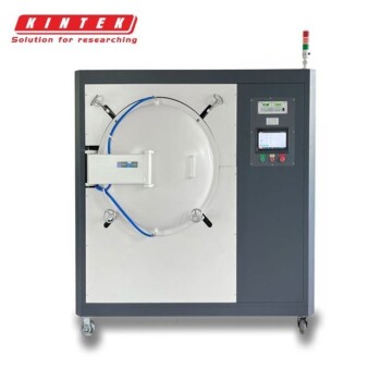
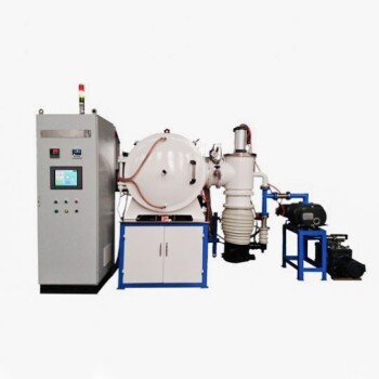
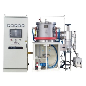
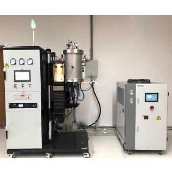
- Vacuum Heat Treat Furnace with Ceramic Fiber Liner
- 2200 ℃ Graphite Vacuum Heat Treat Furnace
- 2200 ℃ Tungsten Vacuum Heat Treat and Sintering Furnace
- Vacuum Heat Treat Sintering Furnace Molybdenum Wire Vacuum Sintering Furnace
- Vacuum Heat Treat Sintering Furnace with Pressure for Vacuum Sintering
People Also Ask
- What are the benefits of using vacuum heat treating furnaces for metal alloys? Achieve Superior Metal Properties and Performance
- What is one of the most important uses of vacuum heat treating furnaces in aerospace? Achieve Superior Strength in Aircraft Alloys
- How does vacuum heat treating work in terms of temperature and time control? Master Precise Material Transformations
- How does vacuum heat treating affect the grain structure of metal alloys? Achieve Precise Microstructure Control
- What is the difference between heat treat and vacuum heat treat? Achieve Superior Metal Properties with Pristine Finishes