At its core, a Chemical Vapor Deposition (CVD) reaction chamber is a highly controlled environment designed to grow a solid thin film onto a surface from a gaseous state. Its main components include a gas delivery system with mass flow controllers, the reaction chamber itself (often a quartz tube) with a substrate holder, a heating system to provide thermal energy, various sensors for monitoring, and an exhaust system to safely handle by-products.
A CVD chamber is not merely a collection of parts, but a sophisticated system where each component works in concert to precisely manage a chemical reaction at the molecular level, transforming gas precursors into a solid material.
The Core Principle: Managing the Flow of a Reaction
A CVD system is engineered to execute a three-step process: introducing reactive gases, energizing them to react, and depositing the resulting solid onto a substrate. Each component cluster serves one of these fundamental stages.
Step 1: Introducing the Precursors
The entire process begins with the precise delivery of reactive gases, known as precursors.
The gas delivery system is the starting point. This includes high-purity gas sources and stainless steel feed lines that transport the gases from the source to the chamber without introducing contaminants.
To ensure the chemical reaction is consistent and repeatable, the gas flow is meticulously regulated by Mass Flow Controllers (MFCs). These devices measure and control the volume of each gas entering the chamber, defining the exact chemical recipe for the film.
Step 2: Creating the Reaction Environment
Once inside the chamber, the precursors must be activated under specific conditions to initiate the chemical reaction.
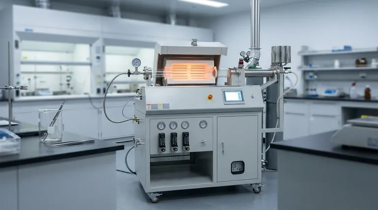
The reaction chamber is the heart of the system. For many applications, this is a quartz tube chosen for its high purity and ability to withstand extreme temperatures without reacting with the process gases. Inside, a substrate holder positions the material to be coated.
Heating sources, often placed at the ends of or surrounding the tube, provide the thermal energy required to break down the precursor gases. The temperature must be uniform and stable.
Temperature and pressure sensors are critical feedback components. They constantly monitor the internal environment, allowing the system to maintain the exact conditions needed for the desired film properties.
Step 3: Deposition and Exhaust
The final stage involves the formation of the solid film and the safe removal of any gaseous waste.
As the energized precursors react on or near the hot substrate, they form a solid material that deposits atom by atom, creating a uniform thin film.
Simultaneously, the reaction creates gaseous by-products which, along with any unreacted precursors, must be removed. The exhaust system draws these gases out of the chamber, often treating them through scrubbers or burn boxes to neutralize any toxic or harmful components before release.
Understanding the Trade-offs and Variations
Not all CVD systems are identical. The choice of components is dictated by the specific material being deposited and the required process conditions.
Hot-Wall vs. Cold-Wall Reactors
In a hot-wall reactor, the entire chamber is heated. This provides excellent temperature uniformity but can lead to deposition on the chamber walls, consuming precursors and creating particles.
In a cold-wall reactor, only the substrate holder is heated. This is more efficient and minimizes wall deposition, but it can create thermal gradients that affect film uniformity.
The Role of Pressure and Plasma
Atmospheric Pressure CVD (APCVD) is simpler and faster but may result in lower-quality films. Low-Pressure CVD (LPCVD) operates under a vacuum, improving film uniformity and purity at the cost of slower deposition rates.
Plasma-Enhanced CVD (PECVD) systems include an additional major component: a plasma generator. The plasma provides energy to the precursors, allowing deposition to occur at much lower temperatures. This is critical for coating temperature-sensitive substrates like plastics.
Making the Right Choice for Your Goal
The configuration of a CVD chamber directly maps to its intended application.
- If your primary focus is research and development: You need maximum precision, requiring high-accuracy Mass Flow Controllers, multiple temperature sensors, and a high-purity quartz chamber.
- If your primary focus is high-volume production: You need a large-capacity chamber, robust heating elements for thermal stability, and an efficient, automated gas delivery system for batch processing.
- If your primary focus is coating heat-sensitive materials: You must use a PECVD system, which requires adding a radio-frequency (RF) plasma source to the component list.
Ultimately, understanding each component's role empowers you to select or design a system that can reliably produce the exact material you need.
Summary Table:
| Component | Function | Key Details |
|---|---|---|
| Gas Delivery System | Introduces and controls reactive gases | Includes mass flow controllers (MFCs) for precise flow regulation |
| Reaction Chamber | Houses the deposition process | Often a quartz tube for purity and high-temperature resistance |
| Heating System | Provides thermal energy for reactions | Ensures uniform temperature for consistent film growth |
| Sensors | Monitors process conditions | Temperature and pressure sensors for real-time feedback |
| Exhaust System | Removes by-products safely | Handles gases with scrubbers to neutralize harmful components |
Ready to enhance your laboratory's capabilities with a tailored CVD solution? At KINTEK, we leverage exceptional R&D and in-house manufacturing to provide advanced high-temperature furnace systems, including CVD/PECVD systems. Our deep customization ensures precise alignment with your unique experimental needs, whether for research, production, or heat-sensitive materials. Contact us today to discuss how our expertise can drive your innovations forward!
Visual Guide

Related Products
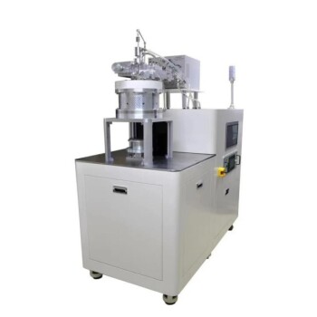
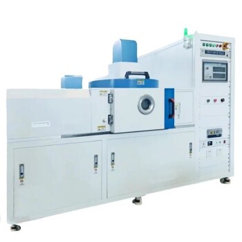
- Split Chamber CVD Tube Furnace with Vacuum Station CVD Machine
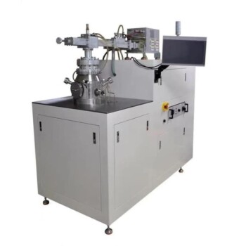
- Custom Made Versatile CVD Tube Furnace Chemical Vapor Deposition CVD Equipment Machine
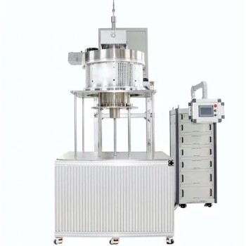
- MPCVD Machine System Reactor Bell-jar Resonator for Lab and Diamond Growth
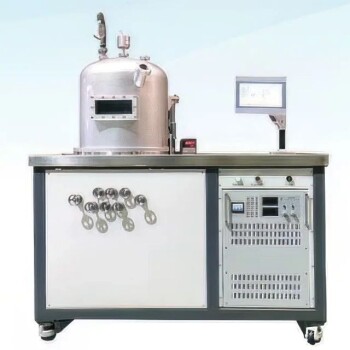
- Slide PECVD Tube Furnace with Liquid Gasifier PECVD Machine
- Multi Heating Zones CVD Tube Furnace Machine for Chemical Vapor Deposition Equipment
People Also Ask
- What role does a Tube Furnace play in the CVD growth of carbon nanotubes? Achieve High-Purity CNT Synthesis
- How might AI and machine learning enhance CVD tube furnace processes? Boost Quality, Speed, and Safety
- Why are CVD tube furnace sintering systems indispensable for 2D material research and production? Unlock Atomic-Scale Precision
- What are the advantages of using a CVD tube furnace for preparing gate dielectrics? Achieve High-Quality Thin Films for Transistors
- What are the practical applications of gate media prepared by CVD tube furnaces? Unlock Advanced Electronics and More