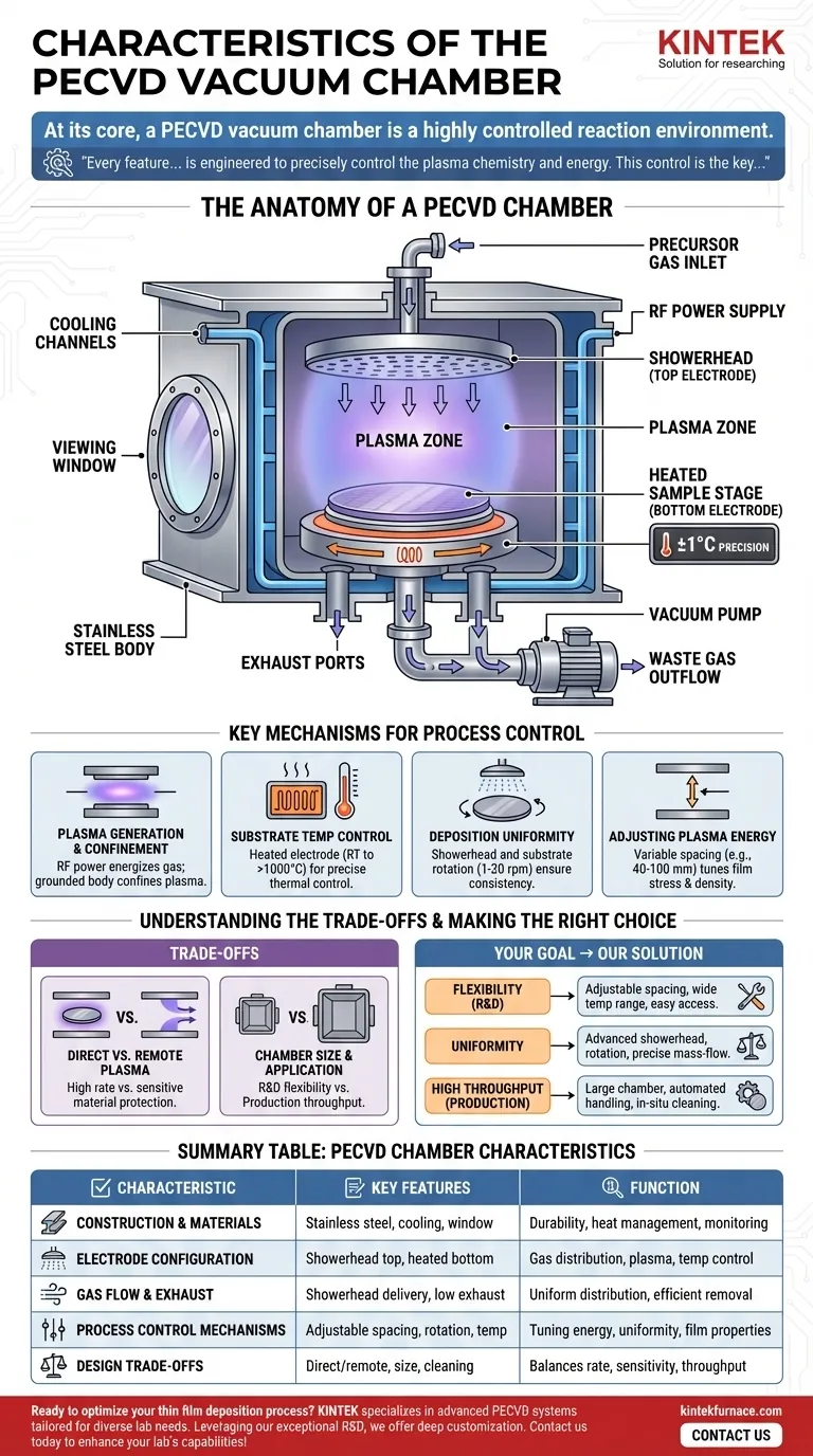
At its core, a PECVD vacuum chamber is a highly controlled reaction environment. Its primary characteristics include a stainless steel body, an internal electrode assembly for generating plasma, a heated stage for the substrate, and a precise gas delivery system. These components work in unison to create the low-pressure, energized conditions necessary for depositing high-quality thin films at relatively low temperatures.
The design of a PECVD chamber is not arbitrary; every feature—from the material choice to the electrode spacing—is engineered to precisely control the plasma chemistry and energy. This control is the key to depositing uniform, high-quality films at temperatures much lower than traditional chemical vapor deposition (CVD) methods.
The Anatomy of a PECVD Chamber
The physical and functional design of the chamber directly enables the PECVD process. Each component serves a specific purpose in creating a stable and uniform deposition environment.
Construction and Materials
The chamber itself forms the vacuum-sealed boundary for the process. It is typically built from stainless steel due to the material's durability, vacuum compatibility, and resistance to chemical corrosion from process gases.
Many chambers also feature integral cooling channels within the walls. This is crucial for managing the significant heat generated by both the plasma and the substrate heater, ensuring the chamber walls remain at a stable temperature.
For process monitoring, a viewing window is standard. This port allows operators or optical sensors to observe the plasma glow, which can be a valuable diagnostic tool.
The Electrode Configuration
PECVD systems most commonly use a capacitive coupling design with two parallel electrodes inside the chamber.
The top electrode is typically a showerhead. This component has a dual function: it distributes precursor gases evenly across the substrate surface and also serves as one of the RF-powered electrodes for igniting the plasma.
The bottom electrode is the sample stage or platen, which holds the substrate. This stage is almost always heated to provide the thermal energy needed for the chemical reactions on the substrate surface.
Gas Flow and Exhaust
Uniform film deposition is impossible without uniform gas delivery. The showerhead design is the most critical feature for this, ensuring that fresh reactant gases are supplied consistently over the entire wafer.
To maintain process stability and remove reaction byproducts, exhaust ports are strategically placed, often below the level of the substrate. This creates a downward flow path that efficiently sweeps away waste gases without disturbing the plasma or incoming reactants.
Key Mechanisms for Process Control
The characteristics of the chamber are what give operators the levers to control the final film properties. The geometry and features are directly linked to process outcomes.
Plasma Generation and Confinement
The chamber's primary role is to contain a low-pressure gas. An RF power supply energizes the electrodes, stripping electrons from the gas molecules and creating plasma. The chamber's sealed, grounded metal body helps confine this plasma between the electrodes where the deposition occurs.
Substrate Temperature Control
The heated lower electrode provides precise thermal control, with accuracy often within ±1°C. This temperature is a critical parameter, influencing film properties like stress, density, refractive index, and chemical composition. Temperatures can range from room temperature to over 1000°C depending on the specific application.
Deposition Uniformity
Two key features work together to ensure the deposited film has a consistent thickness across the entire substrate. The showerhead provides uniform gas flow, while substrate rotation (typically 1-20 rpm) averages out any remaining asymmetries in the plasma density or temperature profile.
Adjusting Plasma Energy
The physical spacing between the showerhead and the sample stage is often adjustable (e.g., from 40-100 mm). Changing this gap alters the electric field strength, which in turn modifies the plasma density and the energy of ions bombarding the substrate. This is a powerful tool for tuning film stress and density.
Understanding the Trade-offs
The specific design of a PECVD chamber involves balancing competing requirements based on its intended use.
Direct vs. Remote Plasma
Most chambers described here are for direct PECVD, where the substrate is immersed directly in the plasma. This provides high deposition rates but also exposes the substrate to ion bombardment. For sensitive materials, chambers can be designed for remote plasma, where the plasma is generated in a separate section and only the reactive chemical species flow to the substrate.
Chamber Size vs. Application
Smaller chambers (e.g., 200-300 mm diameter) are common in research and development. They allow for rapid process cycles, easy cleaning, and material flexibility. Larger chambers are used in production to accommodate bigger substrates or batches, prioritizing throughput and automation over flexibility.
Material Compatibility and Cleaning
While stainless steel is robust, film deposition inevitably occurs on the chamber walls, not just the substrate. The chamber must be designed for easy cleaning, either manually through a large front door or via automated in-situ plasma cleaning cycles using corrosive gases like nitrogen trifluoride (NF3).
Making the Right Choice for Your Goal
The ideal PECVD chamber configuration depends directly on your primary objective.
- If your primary focus is research and development: Prioritize chambers with maximum flexibility, such as adjustable electrode spacing, a wide temperature range, and easy access for modification.
- If your primary focus is process uniformity: Look for systems with advanced showerhead designs, substrate rotation capabilities, and precise mass-flow control for gas delivery.
- If your primary focus is high throughput for production: Select larger chambers designed for automated wafer handling and equipped with robust in-situ plasma cleaning capabilities to maximize uptime.
Ultimately, understanding these characteristics empowers you to select or design a system where the chamber itself becomes a predictable tool for achieving your desired film properties.
Summary Table:
| Characteristic | Key Features | Function |
|---|---|---|
| Construction and Materials | Stainless steel body, integral cooling channels, viewing window | Ensures durability, vacuum sealing, heat management, and process monitoring |
| Electrode Configuration | Showerhead top electrode, heated bottom electrode | Distributes gases evenly, generates plasma, and controls substrate temperature |
| Gas Flow and Exhaust | Showerhead gas delivery, exhaust ports below substrate | Provides uniform gas distribution and efficient removal of byproducts |
| Process Control Mechanisms | Adjustable electrode spacing, substrate rotation, precise temperature control | Enables tuning of plasma energy, deposition uniformity, and film properties |
| Design Trade-offs | Direct vs. remote plasma, chamber size, material compatibility | Balances deposition rate, substrate sensitivity, throughput, and cleaning ease |
Ready to optimize your thin film deposition process? KINTEK specializes in advanced high-temperature furnace solutions, including PECVD systems tailored for diverse laboratory needs. Leveraging our exceptional R&D and in-house manufacturing, we offer deep customization to precisely meet your unique experimental requirements—whether for research, uniformity, or high-throughput production. Contact us today to discuss how our expertise can enhance your lab's capabilities and achieve superior results!
Visual Guide
Related Products
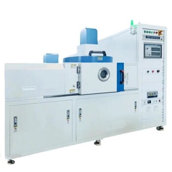
- RF PECVD System Radio Frequency Plasma Enhanced Chemical Vapor Deposition
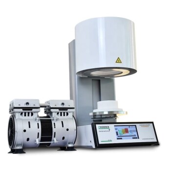
- Slide PECVD Tube Furnace with Liquid Gasifier PECVD Machine
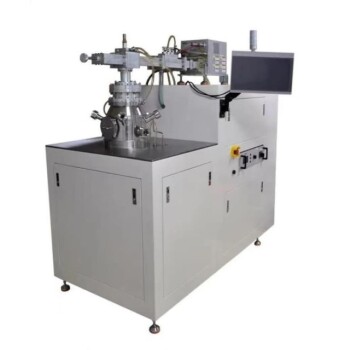
- Split Chamber CVD Tube Furnace with Vacuum Station CVD Machine
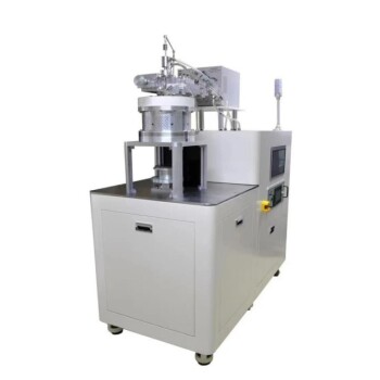
- Inclined Rotary Plasma Enhanced Chemical Deposition PECVD Tube Furnace Machine
- Inclined Rotary Plasma Enhanced Chemical Deposition PECVD Tube Furnace Machine
People Also Ask
- How is silicon dioxide deposited from tetraethylorthosilicate (TEOS) in PECVD? Achieve Low-Temperature, High-Quality SiO2 Films
- What are the advantages of PECVD in film deposition? Achieve Low-Temp, High-Quality Coatings
- What is the role of RF power in PECVD and how does the RF-PECVD process work? Master Thin Film Deposition Control
- How does film quality compare between PECVD and CVD? Choose the Best Method for Your Substrate
- What is PECVD specification? A Guide to Choosing the Right System for Your Lab