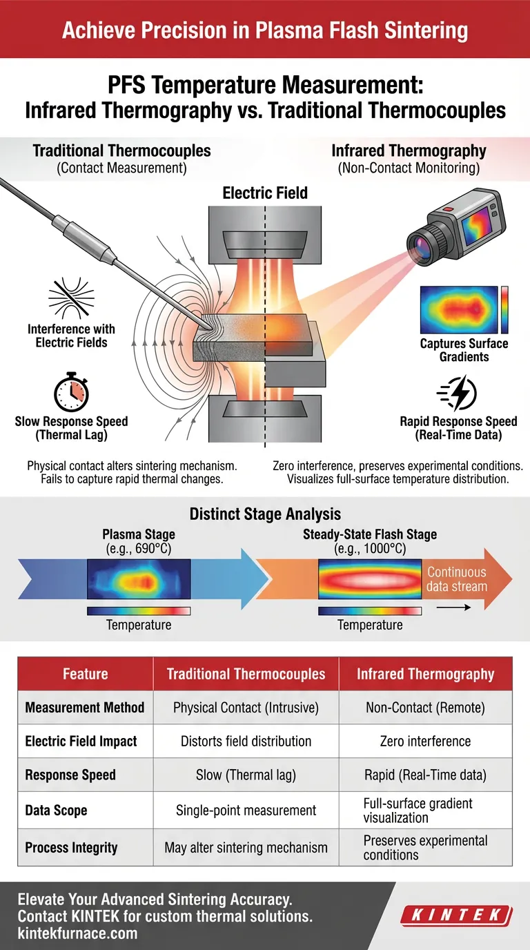
Infrared thermography provides a decisive advantage in Plasma Flash Sintering (PFS) by eliminating the physical contact that compromises traditional measurement methods. Unlike thermocouples, an infrared thermograph offers the rapid response speed necessary to capture real-time data without interfering with the sensitive electric field distribution required for the sintering process.
The core challenge in PFS is measuring temperature without altering the physics of the process. Infrared thermography solves this by enabling non-invasive, real-time observation of temperature gradients, ensuring data accuracy from the initial plasma discharge through the final flash stage.
The Limitations of Contact Measurement
To understand the value of infrared thermography, one must first recognize why traditional methods fail in this specific environment.
Interference with Electric Fields
Plasma Flash Sintering relies heavily on precise electrical discharge. Traditional contact thermocouples are intrusive. By physically touching the sample, they can interfere with the electric field distribution, potentially altering the sintering mechanism itself.
Inability to Track Heating Rates
PFS is characterized by extremely high heating rates. Thermocouples often lack the response speed required to keep up with these rapid thermal changes. This lag results in data that fails to reflect the true, instantaneous state of the material.
The Strategic Edge of Infrared Thermography
Switching to an infrared thermograph allows for a deeper understanding of the thermal mechanisms at play during PFS.
Non-Contact Real-Time Monitoring
The primary benefit is the ability to monitor the process remotely. This non-contact approach ensures that the electric field remains undisturbed, maintaining the integrity of the experimental conditions.
Capturing Surface Gradients
Unlike a thermocouple, which measures a single point, an infrared thermograph captures the entire surface. It precisely visualizes temperature distribution gradients, revealing how heat propagates across the sample geometry.
Distinct Stage Analysis
The tool is sensitive enough to distinguish between the critical phases of the process. It accurately captures thermal data during the plasma stage (e.g., 690°C) and the subsequent steady-state flash stage (e.g., 1000°C), providing a complete thermal history.
Common Pitfalls to Avoid
When selecting instrumentation for PFS, understanding the risks of the wrong tool is just as important as knowing the benefits of the right one.
The Illusion of Contact Accuracy
It is a common mistake to assume a physical sensor is always more accurate. In an electrically active environment like PFS, physical contact creates distortion. Relying on thermocouples here does not just yield slow data; it yields data from a process that has been fundamentally altered by the sensor's presence.
Overlooking Response Latency
Do not underestimate the speed of the "flash" event. Using sensors with high thermal mass or slow response times will smooth out the data peaks. This causes you to miss the critical transient spikes that define the flash sintering phenomenon.
Making the Right Choice for Your Goal
The choice between measurement tools defines the quality of your process insight.
- If your primary focus is process integrity: Choose infrared thermography to avoid interfering with the electric field distribution essential for sintering.
- If your primary focus is thermal mechanism analysis: Use infrared thermography to visualize real-time surface gradients and distinct heating stages.
By adopting non-contact monitoring, you move from estimating the process to accurately visualizing the thermal physics of Plasma Flash Sintering.
Summary Table:
| Feature | Traditional Thermocouples | Infrared Thermography |
|---|---|---|
| Measurement Method | Physical Contact (Intrusive) | Non-Contact (Remote) |
| Electric Field Impact | Distorts field distribution | Zero interference |
| Response Speed | Slow (Thermal lag) | Rapid (Real-time data) |
| Data Scope | Single-point measurement | Full-surface gradient visualization |
| Process Integrity | May alter sintering mechanism | Preserves experimental conditions |
Elevate Your Advanced Sintering Accuracy with KINTEK
Precision is the backbone of successful materials science. KINTEK provides the high-performance thermal solutions you need to master complex processes like Plasma Flash Sintering.
Backed by expert R&D and world-class manufacturing, we offer a comprehensive range of Muffle, Tube, Rotary, Vacuum, and CVD systems, along with specialized lab high-temp furnaces—all fully customizable to your unique research specifications. Don't let measurement interference or equipment limitations compromise your data.
Ready to optimize your thermal processing? Contact KINTEK today to discuss your custom furnace needs and see how our expertise can drive your innovation forward.
Visual Guide
References
- Eva Gil‐González, Luis A. Pérez‐Maqueda. Plasma‐flash sintering: Metastable phase stabilization and evidence of ionized species. DOI: 10.1111/jace.20105
This article is also based on technical information from Kintek Furnace Knowledge Base .
Related Products
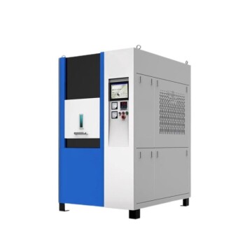
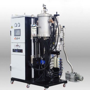
- Spark Plasma Sintering SPS Furnace
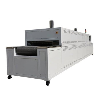
- High Temperature Muffle Oven Furnace for Laboratory Debinding and Pre Sintering
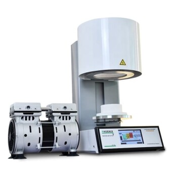
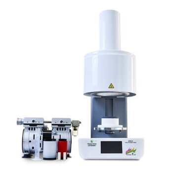
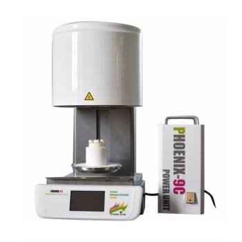
- Vacuum Dental Porcelain Sintering Furnace for Dental Laboratories
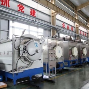
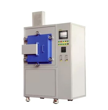
- Vacuum Heat Treat Sintering and Brazing Furnace
- Dental Porcelain Zirconia Sintering Ceramic Vacuum Press Furnace
People Also Ask
- What are the technical advantages of using an SPS sintering furnace? Elevate Al2O3-TiC Material Performance
- What are the steps in the discharge plasma sintering process? Master Fast, High-Density Material Consolidation
- What are the advantages of using a Spark Plasma Sintering (SPS) furnace? Achieve Rapid Densification and High ZT
- What is unique about the heating mechanism of a Spark Plasma Sintering (SPS) furnace when preparing nanostructured h-BN ceramics? Achieve Ultra-Fast Densification and Suppress Grain Growth
- What is sintering in dentistry? The Key to Durable, High-Strength Dental Restorations