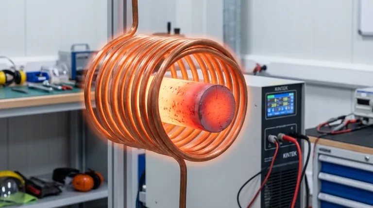
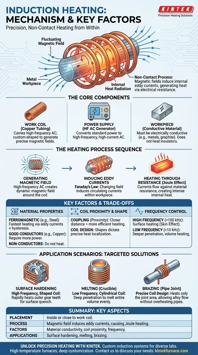
In an induction heating system, the target material, or "workpiece," is placed directly inside or very close to a copper coil. A high-frequency alternating current flowing through this coil generates a powerful magnetic field, which induces internal electrical currents called eddy currents within the workpiece. As these currents flow against the material's own electrical resistance, they generate intense heat, causing the object to heat up rapidly from the inside out.
The core principle to understand is that induction is a non-contact heating method. It doesn't use an external flame or heating element; instead, it uses magnetic fields to turn the target material itself into the source of the heat.
The Core Components of an Induction System
To understand the process, you must first understand the key players involved. An induction heater is a system, not just a single part.
The Work Coil
The most visible component is the work coil, which is typically a hollow tube made of highly conductive copper. A high-frequency alternating current (AC) is passed through this coil. It is custom-shaped to fit around or near the part being heated.
The Power Supply
The work coil is connected to a specialized power supply. Its job is to convert standard electrical power into the high-frequency, high-current AC needed to drive the coil and generate the powerful magnetic field.
The Workpiece (Target Material)
This is the object you intend to heat. For induction to work, the workpiece must be electrically conductive. Materials like metals and graphite are excellent candidates, whereas materials like plastic, glass, or ceramic will not heat directly.
How Magnetic Fields Create Internal Heat
The heating process occurs in a precise, near-instantaneous sequence. It is governed by two fundamental principles of physics: Faraday's Law of Induction and the Joule effect.
Step 1: Generating the Magnetic Field
When the high-frequency AC from the power supply flows through the copper work coil, it generates a dynamic and intense magnetic field in the space within and around the coil. The direction of this field changes thousands or millions of times per second, in sync with the current.
Step 2: Inducing Eddy Currents
According to Faraday's Law, a changing magnetic field will induce a current in any conductor placed within it. When you place the metal workpiece inside the coil, the powerful, fluctuating magnetic field induces circulating electrical currents within the workpiece itself. These are the eddy currents.
Step 3: Heating Through Resistance (Joule Heating)
All materials have some electrical resistance. As these induced eddy currents swirl through the workpiece, they encounter this resistance. The friction generated by the electrons flowing against the material's resistance creates intense, localized heat. This is known as Joule heating, and it is what makes the material's temperature rise so quickly.
Understanding the Trade-offs and Key Factors
The effectiveness of induction heating is not universal; it depends heavily on the material, frequency, and system design.
Material Properties are Paramount
The process works best with ferromagnetic materials like iron and steel because they also heat through a secondary effect called hysteresis loss, making them heat exceptionally fast. Good conductors like copper and aluminum can be heated, but they require more power. Non-conductive materials cannot be heated by induction at all.
Coil Proximity and Shape Dictate Precision
The magnetic field is strongest closest to the coil. The closer the workpiece is to the coil (a concept called "coupling"), the more efficient the heating process will be. The shape of the coil is engineered to control exactly which part of the workpiece heats up, allowing for incredible precision.
Frequency Controls Heating Depth
The frequency of the alternating current is a critical variable. High frequencies (e.g., >100 kHz) tend to heat only the surface of the material, a phenomenon known as the "skin effect." Low frequencies (e.g., <10 kHz) penetrate deeper, heating more of the material's total volume.
Making the Right Choice for Your Goal
By controlling these factors, induction heating can be adapted to a wide range of industrial and technical applications.
- If your primary focus is surface hardening a steel gear: Use a high-frequency current and a coil shaped to match the gear's teeth to rapidly heat and then quench only the outer surface.
- If your primary focus is melting a crucible of metal: Use a lower frequency and a cylindrical coil to ensure the magnetic field penetrates deeply and heats the entire volume of the material evenly.
- If your primary focus is brazing two copper pipes together: Design a coil that specifically heats the joint area, allowing the brazing alloy to flow into the gap without overheating the rest of the pipes.
Understanding these principles transforms induction heating from a mysterious process into a precise and controllable manufacturing tool.
Summary Table:
| Aspect | Details |
|---|---|
| Placement | Inside or close to a copper work coil |
| Process | Magnetic field induces eddy currents, causing internal heating (Joule effect) |
| Key Factors | Material conductivity, coil proximity, frequency (affects depth) |
| Applications | Surface hardening, melting, brazing for metals and graphite |
Unlock Precision Heating with KINTEK
Leveraging exceptional R&D and in-house manufacturing, KINTEK provides diverse laboratories with advanced high-temperature furnace solutions. Our product line, including Muffle, Tube, Rotary Furnaces, Vacuum & Atmosphere Furnaces, and CVD/PECVD Systems, is complemented by our strong deep customization capability to precisely meet unique experimental requirements. For tailored induction heating systems that enhance efficiency and accuracy in your lab, contact us today to discuss your specific needs and see how we can drive your innovations forward!
Visual Guide
Related Products
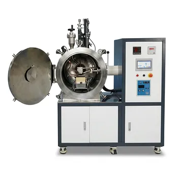
- 600T Vacuum Induction Hot Press Vacuum Heat Treat and Sintering Furnace
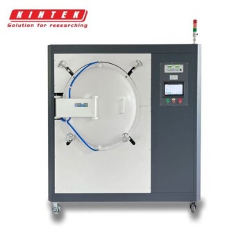
- Vacuum Induction Melting Furnace
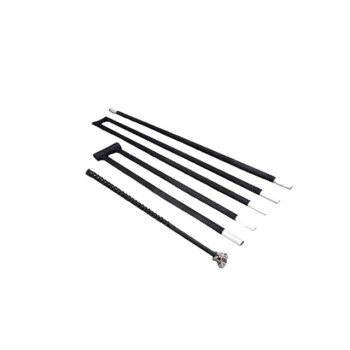
- Silicon Carbide SiC Thermal Heating Elements for Electric Furnace
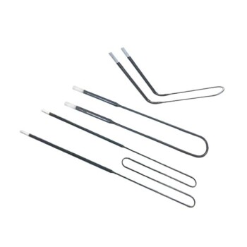
- Molybdenum Disilicide MoSi2 Thermal Heating Elements for Electric Furnace
- Vacuum Heat Treat Furnace with Ceramic Fiber Liner
People Also Ask
- How does the furnace cooling method protect CoCrFeNi(Cu) coatings after vacuum hot pressing sintering? Prevent Cracking & Oxidation for Superior Performance
- What are the advantages of using a vacuum hot press sintering furnace for preparing high-density carbon nanotube reinforced copper matrix composites? Achieve Maximum Density and Purity for Superior Performance
- How does the vacuum environment in a vacuum hot press sintering furnace protect chromium-containing ceramics? Find out.
- How does a vacuum hot press sintering furnace mitigate copper sintering swelling? Solve Fe-Cu Expansion Issues
- What are the key advantages of vacuum hot press sintering furnaces? Achieve Superior Density and Purity in Materials