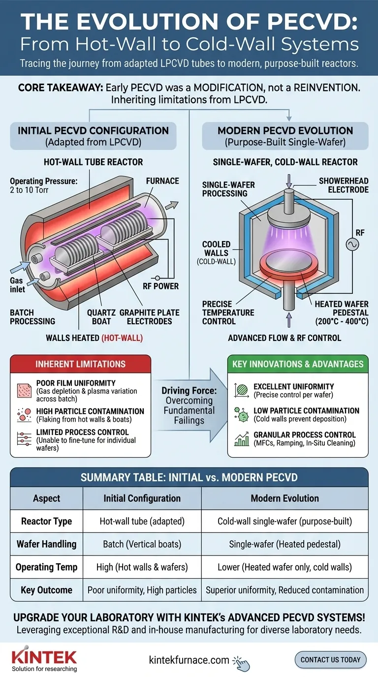
Initially, the first commercial Plasma Enhanced Chemical Vapor Deposition (PECVD) systems were not revolutionary new designs. Instead, they were pragmatic adaptations of the prevailing technology of their time: Low Pressure Chemical Vapor Deposition (LPCVD). These early systems were built around an evacuated hot-wall tube reactor, operating at pressures between 2 and 10 Torr, which directly mirrored the configuration of existing LPCVD furnaces.
The core takeaway is that early PECVD was a modification, not a reinvention. By inserting electrodes into existing hot-wall LPCVD tube reactors, engineers created a plasma process, but this approach inherited all the fundamental limitations of its predecessor, particularly poor uniformity and particle contamination.
The Foundation: Adapting LPCVD Technology
The goal of early PECVD was to achieve deposition at lower temperatures than LPCVD, but the hardware was a direct evolution of what was already in use for high-temperature processes.
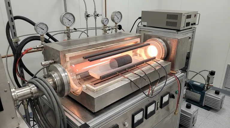
The Hot-Wall Tube Reactor
The central component of these first-generation systems was a large quartz tube furnace. This tube was heated externally, meaning the walls of the reactor were just as hot as the substrates being processed.
Inside this tube, silicon wafers were loaded vertically in quartz "boats," allowing dozens or even hundreds of wafers to be processed in a single batch.
Introducing the Plasma
To transform an LPCVD system into a PECVD system, electrodes were placed inside the tube. These were typically parallel graphite plates that ran along the length of the reactor, positioned between the wafer boats.
When radio frequency (RF) power was applied to these electrodes, a plasma was generated from the precursor gases, enabling deposition to occur on the wafer surfaces at a much lower temperature.
Initial Operating Conditions
These batch systems operated in a medium vacuum range of 2 to 10 Torr. This pressure was necessary to sustain a stable plasma throughout the large volume of the tube reactor.
Understanding the Inherent Limitations
While functional, borrowing the hot-wall architecture brought significant and predictable problems, which the provided references describe as "similar failings to hot wall LPCVD."
Poor Film Uniformity
In a long, hot tube, gas reactants are consumed as they flow from the inlet to the exhaust. This "gas depletion" effect meant wafers at the front of the tube were exposed to a different gas concentration than wafers at the back, leading to variations in film thickness and properties across the batch. The plasma density also varied along the length of the tube, compounding the uniformity issue.
High Particle Contamination
Because the entire tube wall was hot, deposition occurred everywhere—not just on the wafers. This unwanted film on the reactor walls and wafer boats would flake off during temperature cycling, generating particles that could fall onto the wafers and cause device-killing defects.
Limited Process Control
A batch tube reactor offers very little individual control. The entire batch of wafers is subjected to the same temperature and plasma conditions. It was impossible to fine-tune parameters for a specific wafer or make rapid process adjustments, a key requirement for advanced semiconductor manufacturing.
The Evolution Toward Modern PECVD
The failings of the hot-wall tube design directly drove the development of the single-wafer, cold-wall reactors that are standard today.
The Shift to Single-Wafer, Cold-Wall Reactors
Modern PECVD systems process one wafer at a time in a much smaller chamber. Critically, the chamber walls are kept cool while only the lower electrode supporting the wafer is heated, often to temperatures between 200°C and 400°C.
This cold-wall design drastically reduces unwanted deposition on chamber surfaces, leading to a much cleaner process with far fewer particles.
Granular Process Control
Contemporary systems feature advanced controls that were unimaginable in the early tube furnaces. This includes:
- Mass Flow Controllers (MFCs) for precise, repeatable gas delivery.
- Parameter ramping software to change conditions during deposition.
- RF switching for fine-tuning film properties like mechanical stress.
Automation and In-Situ Cleaning
Modern reactors solve the particle problem with in-situ plasma cleaning. After processing a wafer, a cleaning gas is used to create a plasma that etches away any residual film from the chamber interior. This automated step, monitored by endpoint control, ensures a consistently clean environment for every wafer.
Making the Right Choice for Your Goal
Understanding this history is not merely academic; it clarifies the core engineering principles that define modern deposition equipment.
- If your primary focus is process engineering: Recognizing the limitations of hot-wall systems explains why modern single-wafer, cold-wall reactors are the industry standard for high-performance films.
- If your primary focus is equipment design: The evolution from batch tubes to single-wafer chambers highlights the driving need to maximize film uniformity and minimize contamination.
- If your primary focus is academic research: Understanding the initial configurations provides context for historical data and clarifies the fundamental trade-off between the high throughput of batch processing and the high precision of single-substrate systems.
By tracing the journey from adapted LPCVD tubes to purpose-built plasma reactors, we can clearly see how each innovation was a direct response to a fundamental physical limitation.
Summary Table:
| Aspect | Initial PECVD Configuration | Key Limitations |
|---|---|---|
| Reactor Type | Hot-wall tube reactor adapted from LPCVD | Poor film uniformity due to gas depletion and plasma variation |
| Operating Pressure | 2 to 10 Torr | High particle contamination from wall deposition |
| Wafer Handling | Batch processing with vertical quartz boats | Limited process control and inability for fine-tuning |
| Plasma Generation | RF-powered parallel graphite electrodes inside tube | Inefficient plasma stability and uniformity |
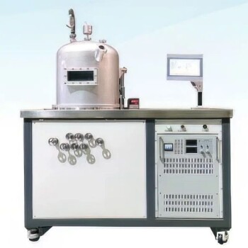
Upgrade your laboratory with KINTEK's advanced PECVD systems! Leveraging exceptional R&D and in-house manufacturing, we provide diverse laboratories with high-temperature furnace solutions tailored to your needs. Our product line, including Muffle, Tube, Rotary Furnaces, Vacuum & Atmosphere Furnaces, and CVD/PECVD Systems, is complemented by strong deep customization capabilities to precisely meet unique experimental requirements. Enhance your research with superior film uniformity and reduced contamination—contact us today to discuss how we can support your goals!
Visual Guide
Related Products
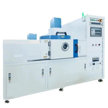
- RF PECVD System Radio Frequency Plasma Enhanced Chemical Vapor Deposition
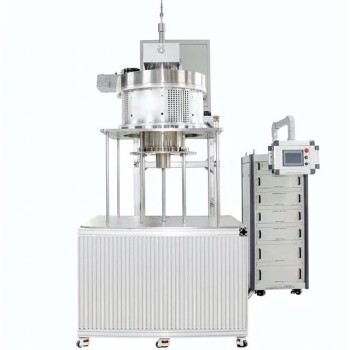
- Slide PECVD Tube Furnace with Liquid Gasifier PECVD Machine
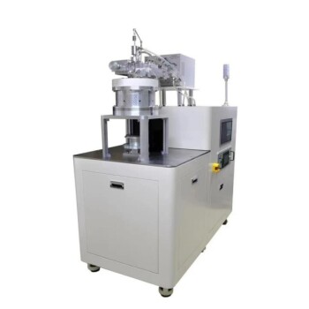
- Inclined Rotary Plasma Enhanced Chemical Deposition PECVD Tube Furnace Machine
- Inclined Rotary Plasma Enhanced Chemical Deposition PECVD Tube Furnace Machine
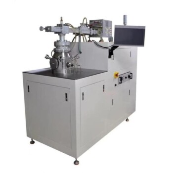
- 915MHz MPCVD Diamond Machine Microwave Plasma Chemical Vapor Deposition System Reactor
People Also Ask
- What is the role of RF power in PECVD and how does the RF-PECVD process work? Master Thin Film Deposition Control
- How does film quality compare between PECVD and CVD? Choose the Best Method for Your Substrate
- What is RF in PECVD? A Critical Control for Plasma Deposition
- What are the applications of plasma enhanced chemical vapor deposition? Key Uses in Electronics, Optics & Materials
- What are the key advantages of PECVD technology? Achieve Low-Temperature, High-Quality Thin Film Deposition