You don't just model the flow—you model the constraint. The numerical modeling of plastic flow in sintered particle-reinforced composites is founded on a microstructure-based constitutive model within a large-deformation Finite Element Analysis (FEA) framework. The core principles involve computational functionals that balance the power of plastic deformation against constraints like material incompressibility and tool-composite friction. The model’s defining characteristic is the extreme yield stress disparity between the soft, ductile matrix and the ultra-hard reinforcement particles, requiring precise calculation of strain gradients at the interfaces. High-temperature laboratory sintering furnaces then make these models physically testable by creating the essential "ground truth": fully consolidated, defect-free, low-porosity compacts whose actual microstructural deformation, observed under electron microscopy, can be directly compared against the simulated strain fields.
The challenge isn't just simulating how a soft matrix flows around a hard particle; it's verifying that a simulation which assumes a perfect, pore-free starting structure holds up in reality. While the numerical model mathematically decomposes the problem into deformation power and tool friction, the physical validation is impossible without a furnace that can produce a near-ideal, fully dense baseline sample. Only then can a researcher trust that a deviation between the model and the micrograph is a flaw in the physics—not a flaw in the processing.
The Numerical Modeling Framework for Plastic Flow
To predict the behavior of a composite during sintering, you must model how the matrix accommodates the presence of rigid, non-deforming particles. This requires a multi-scale numerical strategy that captures both the macroscopic driving forces and the particle-level constraints.
Decomposing the Problem with Finite Element Analysis
The primary modeling strategy relies on three-dimensional FEA built around deformation power functionals. This is not a simple stress-strain curve; it’s a system of equations that computes the total power required to deform the material. The functional explicitly incorporates several competing factors. The first is the plastic deformation power of the ductile matrix itself, often aluminum-based, which dictates the base energy required for flow. This internal power dissipation is then mathematically constrained by a penalty function that enforces material incompressibility, preventing artificial volume changes as the material extrudes and densifies. Finally, the model layers in the tool-material contact friction stress, which accounts for the shear forces at the die wall. These three elements together create a field of strain that concentrates intensely at the surface of each rigid particle, defining the flow.
Bridging Scales with Discrete Element Dynamics
While FEA handles the continuum, the behavior at the particle scale demands a coordinated approach using the Discrete Element Method (DEM). DEM models the powder compact as an assembly of individual particles, calculating inter-particle contact forces, the loss of those contacts during rearrangement, and the alignment of pore channels. This is critical because the fundamental inputs for the macroscopic FEA model—such as the effective shear and bulk viscous moduli of the particle packing—are themselves outputs from DEM simulations. You cannot accurately forecast how a powder bed consolidates without first understanding how the initial particle network transmits force and collapses. The combined DEM-FEM workflow thus allows a researcher to simulate not just the final product’s warping, but the evolution of the microstructure itself.
The Critical Role of High-Temperature Laboratory Furnaces
No numerical model is self-certifying. A high-temperature furnace is not just a heating device; it is the instrument that translates a mathematical boundary condition into a physical test specimen with the precise microstructure the simulation demands.
Creating the Defect-Free Baseline for Model Validation
A simulation of plastic flow around a particle assumes a perfectly bonded, pore-free starting condition. A physical test of this model is invalid if the initial sample contains sintering flaws. High-temperature vacuum or inert atmosphere furnaces are necessary to achieve this. They produce fully consolidated, low-porosity powder metallurgy compacts by delivering the precise thermal energy required for solid-state or liquid-phase diffusion, all while an argon, nitrogen, or vacuum environment prevents oxidation. This consistent processing yields the defect-free baseline microstructure. When that sample is later deformed and analyzed under electron microscopy, researchers can reliably attribute observed strain patterns to the model’s physics, not to pre-existing porosity or contamination.
Overcoming the Retarding Effect Through Precise Profiling
The most significant complication in composite sintering is the retarding effect of rigid inclusions on densification. These particles constrain matrix shrinkage, and this constraint increases with higher inclusion volume fractions. A critical deep need is overcoming this retardation, and the solution lies in the matrix's intrinsic grain growth kinetics. Matrix materials that exhibit minimal grain growth during sintering suffer far less densification inhibition from the rigid particles. A high-temperature laboratory furnace enables the precise thermal profiling needed to exploit this principle. By maintaining a thermal history that promotes densification without rapid grain coarsening, the furnace can guide the matrix to near-theoretical density while preserving a fine grain size, thereby preventing crack-like defects around the inclusions that would catastrophically invalidate any FEA model based on a pristine interface.
Understanding the Trade-offs in Modeling and Verification
The path from a numerical model to a validated physical experiment is filled with critical choices that carry inherent limitations. Trust in the research hinges on acknowledging these trade-offs.
The Resolution vs. Representativeness Challenge
There is a fundamental tension between model detail and computational feasibility. A pure DEM simulation can capture the random packing, particle sliding, and exact pore morphology with high fidelity, but it is computationally prohibitive for modeling a complete bulk component. Conversely, a macroscopic FEA model treats the material as a homogeneous continuum, which may average out the extreme strain localization that causes failure around a single particle. Researchers must decide whether the model's purpose is to predict the onset of a single crack or to forecast the gross distortion of a part, and they must be explicit about this choice when comparing their results to furnace-validated metallography.
The Processing Environment Assumption
The numerical model’s contact friction and deformation power terms are based on an assumption of a consistent chemical interface. If the laboratory furnace does not maintain a perfectly inert atmosphere, the resulting oxide layers or surface chemistries on the aluminum matrix powder will alter the real friction and bonding in ways the FEA model did not capture. The model is a closed system; the furnace must create a physical environment that mirrors this idealization. Any deviation, such as the thermal degradation or phase separation that sintering is specifically designed to avoid, introduces a variable that makes the model appear inaccurate, even if its core physics are correct.
Making the Right Choice for Your Research Validation
Your specific research goal dictates how you should prioritize and integrate these modeling principles and furnace capabilities into a cohesive validation strategy.
- If your primary focus is analyzing fundamental deformation mechanisms at particle interfaces: Prioritize a coupled DEM-FEA approach. Use DEM outputs to feed accurate granular material parameters into a high-resolution FEA model, and use the lab furnace to produce a dense, two-particle analog for precise electron microscope comparison.
- If your primary focus is predicting macroscopic component failure or shape distortion: Lean on the continuum FEA framework with deformation power functionals and tool-friction terms. Your furnace validation should then focus on producing full-scale compacts with a goal of 99% theoretical density, so the bulk mechanical test matches a model that assumes near-ideal consolidation.
- If your primary focus is establishing a credible, defensible baseline material property set: Concentrate on the furnace's ability to eliminate the retarding effect through precise thermal profiling that minimizes grain growth. Validate the model only after metallography confirms a dense, crack-free interface around the rigid inclusions, ensuring your material constants are uncontaminated by processing defects.
Mastering the plastic flow of these composites is about making the simulation and the physical world speak the same language, where the furnace creates the perfect physical expression of the model’s starting assumptions.
Summary Table:
| Modeling Framework | Key Computational Role | Laboratory Furnace Validation Role |
|---|---|---|
| Finite Element Analysis (FEA) | Calculates plastic deformation power, incompressibility, and die friction stress. | Produces 99%+ dense, low-porosity compacts matching ideal continuum flow assumptions. |
| Discrete Element Method (DEM) | Models inter-particle contact forces, sliding, and pore morphology evolution. | Supplies physical baseline microstructures to verify grain-level strain localization fields. |
| Thermal Profiling & Kinetics | Simulates matrix grain growth and inclusion retarding effect constraints. | Delivers precise heating rates to minimize matrix grain coarsening and prevent interface defects. |
Validate Your Material Simulations with Precision Sintering Solutions
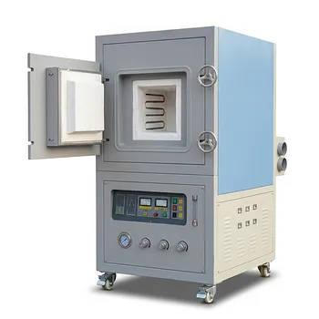
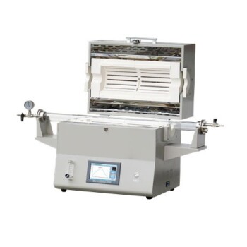
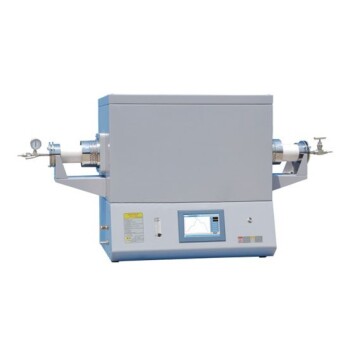
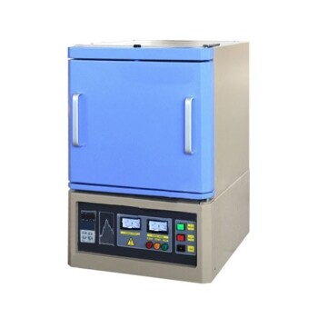
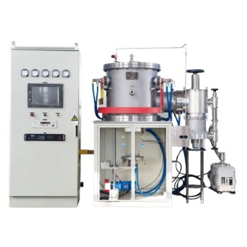
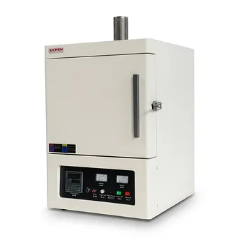
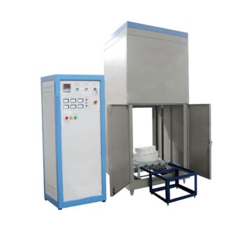
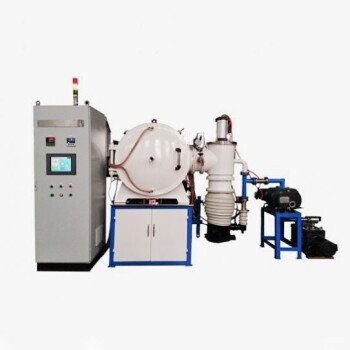
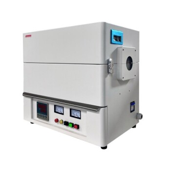
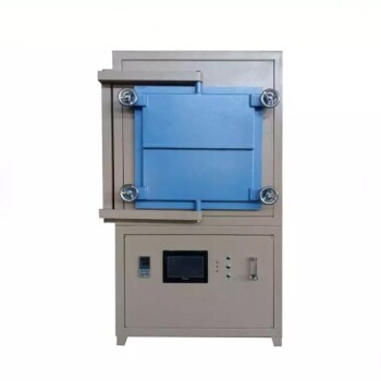
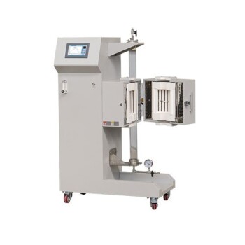
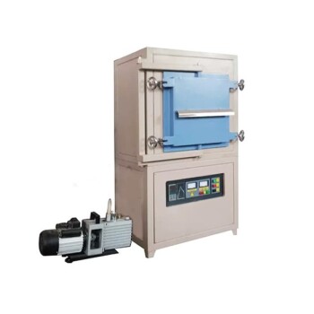
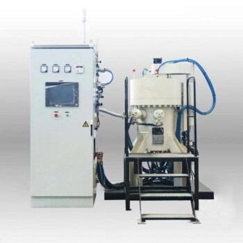
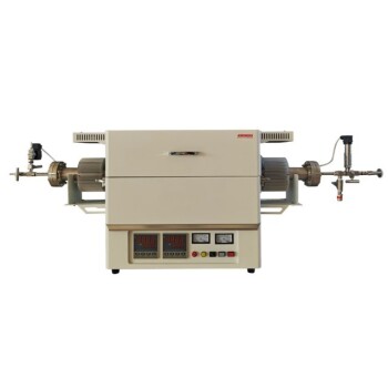
Accurate FEA and DEM models demand defect-free, fully dense baseline samples for physical validation. KINTEK specializes in high-performance laboratory equipment and high-temperature furnaces—including vacuum, atmosphere, tube, muffle, and customizable systems—designed to provide the exact thermal profiling and atmosphere control your research requires.
Eliminate processing defects and transform your numerical models into verified results. Contact KINTEK today to consult with our experts on the ideal furnace solution for your laboratory!
Related Products
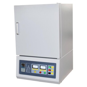
- High Temperature Muffle Oven Furnace for Laboratory Debinding and Pre Sintering
- 1400℃ High Temperature Laboratory Tube Furnace with Alumina Tube
- 1700℃ High Temperature Laboratory Tube Furnace with Alumina Tube
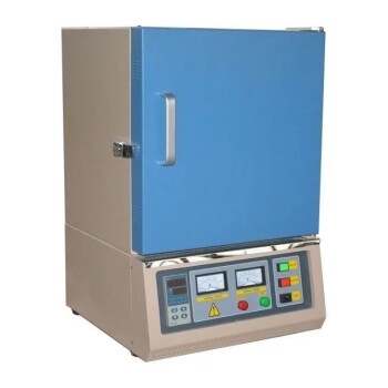
- 1800℃ High Temperature Muffle Oven Furnace for Laboratory
- 1700℃ High Temperature Muffle Oven Furnace for Laboratory
People Also Ask
- What thermal phenomena occur during polymer binder burnout in ceramic green bodies? Lab Furnace Guide
- Why is controlled heat treatment in a muffle furnace necessary for calcined clay? Achieve Optimal Pozzolanic Activity
- What role does a high-temperature muffle furnace play in STFO synthesis? Achieve Pure Perovskite Results
- How does a high-temperature muffle furnace facilitate the formation of LaNbxAl1−xO3+δ perovskite structures? Key Roles
- What role does a high-temperature muffle furnace play in the formation of biochar catalysts? Master Catalyst Synthesis