Mismatched shrinkage is the crack initiator. During co-sintering, localized cracking and transient matrix stresses arise because the sintering matrix tries to shrink around rigid, non-sintering inclusions or substrates, but is mechanically constrained. This constraint generates a tensile hydrostatic backstress that opposes densification and, more critically, a tangential (hoop) tensile stress at the inclusion-matrix interface. When that interfacial tensile stress exceeds the green body’s local strength, radial microcracks nucleate and propagate, damaging the composite.
Core takeaway: The root cause is differential densification. As the fine-grained matrix shrinks, rigid inclusions resist that shrinkage. This fight creates transient tensile hoop stresses around each inclusion, and if those stresses overcome the weak, porous matrix, localized cracking occurs. Simultaneously, a uniform tensile backstress in the matrix slows the overall densification rate, making the process a delicate balance between achieving density and avoiding failure.
The Constrained Sintering Mechanism
When a ceramic matrix composite is heated in a furnace, the porous matrix wants to densify and shrink. Dense, rigid inclusions (particles, whiskers, fibers, or even a rigid substrate) do not shrink at the same rate.
This mismatch creates a mechanical battle. The matrix pulls inward, but the inclusion pushes back, generating transient stress fields that evolve with time and temperature.
How Differential Shrinkage Generates Stress
Because the matrix attempts to shrink around an inclusion that won’t budge, strain compatibility forces the matrix to stretch. This creates a classic composite-sphere stress state.
Inside the inclusion, a purely hydrostatic compressive stress develops. In the surrounding matrix, the same incompatibility produces a uniform tensile hydrostatic backstress that directly opposes the sintering driving force.
At the interface itself, the stress field is not purely hydrostatic. A maximum tangential (hoop) tensile stress acts along the circumference of the inclusion, trying to pull the matrix apart.
Why the Constraint Intensifies During Sintering
As sintering progresses, the matrix volume decreases. This causes the volume fraction of the rigid inclusions to effectively increase. The more the matrix shrinks, the more dominant the inclusions become, progressively amplifying the mechanical constraint.
The result is a non-linear evolution of stress. Even if initial stresses are manageable, they can climb significantly later in the densification curve unless relaxation mechanisms intervene.
Stress Components That Drive Damage
Three distinct but interrelated stress components define the local mechanical state. Understanding each is essential to diagnosing and preventing cracking.
Tensile Hoop Stress: The Crack Initiator
The tangential (hoop) tensile stress at the inclusion-matrix interface is the primary culprit behind localized cracking. It acts like a rubber band being stretched around a solid core—the tension is highest right at the interface.
If this tensile stress exceeds the tensile strength of the porous matrix (which is low in a green or partially sintered body), microstructural flaws or pre-existing pores can open up. Radial microcracks then propagate outward from the inclusion surface into the matrix.
Hydrostatic Backstress: The Densification Brake
Simultaneously, the rigid inclusion imposes a uniform tensile hydrostatic stress throughout the entire matrix region. This tensile backstress subtracts from the inherent compressive sintering stress (the capillary force that drives densification).
The effective driving force for densification is therefore reduced. The composite densifies more slowly than an unconstrained powder compact, and in extreme cases, densification can virtually stall.
Tensile Stress from Closely Spaced Inclusions
When inclusions are spaced more closely than the typical particle size, they form rigid, non-deformable networks. The matrix trapped between these particles experiences an even more severe constraint.
These networks act as a local cage, inhibiting shrinkage in adjacent regions. The result is differential shrinkage zones, which produce localized porous regions, intensifying the mismatch strains and creating crack-like defect nucleation sites.
How Transient Stresses Cause Localized Cracking
The damage does not happen instantaneously. It is a progression driven by the interplay of stress intensity, material strength, and time-dependent relaxation.
The Critical Crack Length Condition
Crack propagation requires both a tensile stress and a flaw. In a porous ceramic matrix, sintering pores act as pre-existing flaws. When a pore near an inclusion experiences a tensile hoop stress sufficient to satisfy the critical crack length criterion, fracture begins.
During furnace heating, the strength of the green body is minimal. The transient tensile stresses peak at intermediate temperatures before significant sintering necks have formed. This is when most cracking events occur.
The Role of Interface Bonding
The interface bonding strength between inclusion and matrix directly influences stress concentration. A well-bonded interface transmits the full mismatch strain into the matrix, generating high tensile stresses.
If the interface is weak, it may slide or partially debond. While this can relieve tensile stress and prevent matrix cracking, it comes at the cost of composite integrity and strength. There’s an inherent trade-off between stress relief and load transfer.
Why a Purely Viscous Model Matters for Predicting Damage
The large strains of sintering are almost entirely viscous; the elastic strain component is negligible. Scherer’s viscous model (based on the elastic–viscous analogy) is preferred because it prevents unrealistic stress overestimations.
This model shows that for non-negative Poisson’s ratios, the maximum transient interfacial stresses remain below twice the sintering stress. This predictable ceiling helps design safe heating profiles: it tells you the worst-case stress your matrix will face, allowing you to keep it below the material’s strength.
Understanding the Trade-offs
Eliminating transient stresses entirely is impossible if rigid inclusions are present. The real goal is managing them.
Inclusion loading increases composite stiffness and functionality, but it directly amplifies backstress and reduces densification rate. Too many inclusions, and the material may never reach full density.
Slow heating allows creep relaxation to dissipate stresses before they reach critical levels, but it extends processing time and can promote grain coarsening. Faster heating may complete densification before creep can relax stresses, risking catastrophic cracking.
Close inclusion spacing enables higher packing fractions but forms rigid networks that generate highly localized cracking. A homogeneous distribution with sufficient matrix bridges is essential.
Multi-layered or co-fired structures introduce additional differential shrinkage between adjacent layers, causing biaxial tensile compatibility stresses that can warp, delaminate, or crack the part. Balancing layer composition, thickness, and firing shrinkage is critical.
Making the Right Choice for Your Process
Your goal determines how you should handle transient matrix stresses during co-sintering.
- If your primary focus is achieving full density: Minimize inclusion loading or use inclusions with a lower stiffness. Accept that you must slow the heating ramp to give creep time to relax the hydrostatic backstress so the sintering driving force can overcome it.
- If your primary focus is component strength and crack avoidance: Keep the maximum transient interfacial tensile stress below the green body’s tensile strength. A viscous model will tell you that staying below twice the sintering stress is a safe bound. Design dwells at intermediate temperatures to allow stress relaxation through viscous flow.
- If your primary focus is processing speed: Increase creep relaxation rates by using finer matrix particles (which enhance diffusional creep) and ensure uniform furnace temperature profiles to avoid adding thermal gradients. Compensate for the slower densification by optimizing the peak temperature, but always verify that hoop stresses never exceed the green strength.
- If your primary focus is multi-layer or co-fired architectures: Match the unconstrained shrinkage rates of adjacent layers as closely as possible. Keep individual layer thicknesses below the critical threshold that triggers crack initiation, and use controlled cooling ramps to manage any residual thermal stresses.
Understanding the precise stress state around every rigid inclusion turns the furnace from a black box into a predictable processing tool. Control the differential shrinkage, and you control the part’s integrity.
Summary Table:
| Stress Component | Core Cause | Microstructural Impact | Mitigation Strategy |
|---|---|---|---|
| Tangential (Hoop) Tensile Stress | Matrix shrinking around rigid, non-sintering inclusions | Nucleates radial microcracks at the matrix interface | Design intermediate temperature dwells; optimize particle spacing |
| Hydrostatic Backstress | Mechanical constraint opposing driving force | Opposes capillary forces, slowing overall densification | Lower inclusion loading; reduce heating rate to allow creep relaxation |
| Network Constraint Stress | Closely spaced inclusions forming rigid cages | Creates localized porous zones and severe stress risers | Ensure homogeneous particle distribution; improve green packing |
| Biaxial Layer Mismatch | Differential shrinkage rates between co-fired layers | Causes warping, layer delamination, and macro-cracking | Match unconstrained layer shrinkage; control individual layer thickness |
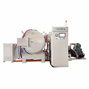
Master precise high-temperature co-sintering and eliminate thermal defects with KINTEK! Defeating transient stresses requires precise thermal control and customized heating environments. KINTEK specializes in advanced laboratory equipment and consumables, offering a comprehensive lineup of high-temperature furnaces—including muffle, tube, rotary, vacuum, CVD, atmosphere, dental, and induction melting systems—all fully customizable to meet your unique material synthesis needs. Enhance your ceramic composite density and structural integrity—contact KINTEK experts today!
Related Products
- 1400℃ High Temperature Laboratory Tube Furnace with Alumina Tube
- 1700℃ High Temperature Laboratory Tube Furnace with Alumina Tube
- 1800℃ High Temperature Muffle Oven Furnace for Laboratory
- 1700℃ High Temperature Muffle Oven Furnace for Laboratory
- 1700℃ Controlled Inert Nitrogen Atmosphere Furnace
People Also Ask
- How does zone-melting in tube furnaces synthesize bismuth micro-wires? Master Single-Crystal Thermoelectric Growth
- How do high-temperature laboratory tube furnaces ensure environmental stability? Precision Thermal Reduction Tips
- How are high-temperature laboratory tube furnaces applied in long-term vacuum homogenization heat treatments for intermetallic samples?
- How are high-temp tube furnaces used to measure diffusion coefficients per Fick's law? Master Precision Annealing
- How are high-temperature tube furnaces applied in testing ceramic-supported alloy membranes? Insights