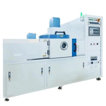
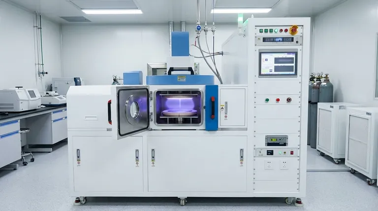
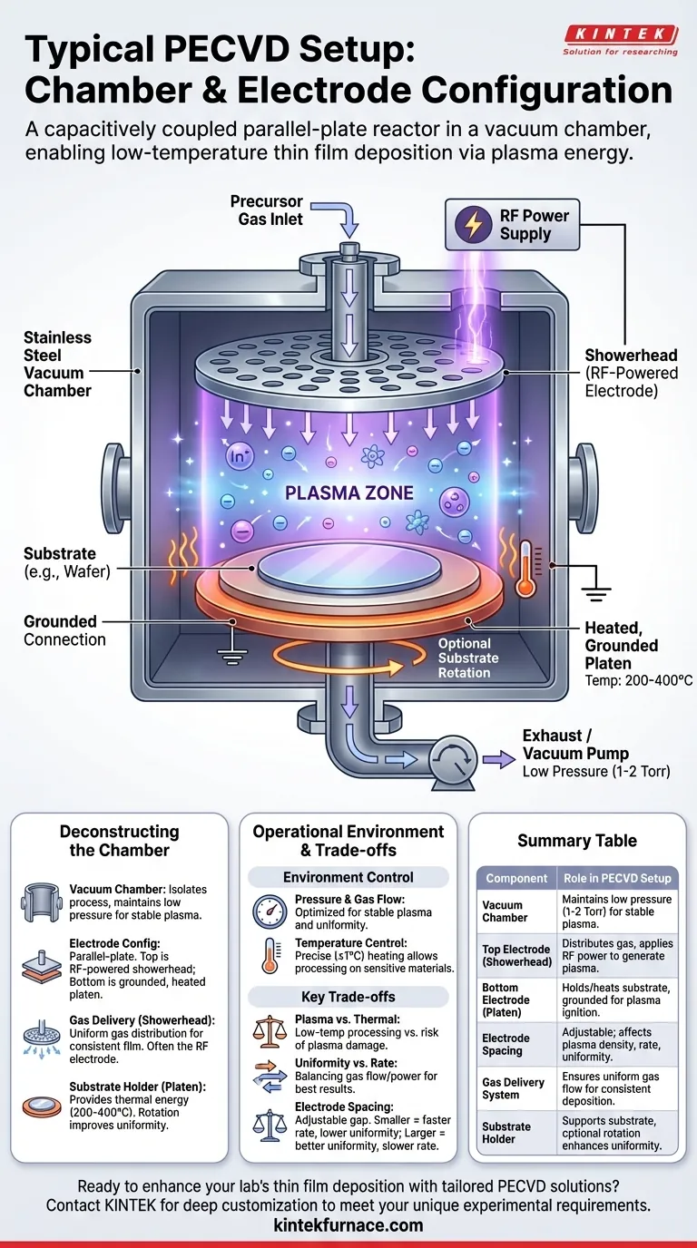
At its core, a typical Plasma-Enhanced Chemical Vapor Deposition (PECVD) system is a capacitively coupled parallel-plate reactor housed within a vacuum chamber. In this setup, precursor gases are introduced through a specialized nozzle called a showerhead, which often doubles as the top, RF-powered electrode. The substrate rests on a heated, grounded lower electrode (platen), and the radio frequency (RF) energy ignites a plasma between these two plates, driving the chemical reactions needed for film deposition at relatively low temperatures.
The fundamental design of a PECVD system is engineered to create a controlled, low-pressure plasma environment. This use of plasma energy, rather than high thermal energy, is the key that enables the deposition of high-quality thin films on substrates that cannot withstand high temperatures.
Deconstructing the PECVD Chamber
To understand the process, we must first understand the primary components of the physical system and the role each one plays.
The Vacuum Chamber
The entire process occurs within a vacuum chamber, typically constructed from stainless steel. This chamber isolates the process from the outside atmosphere.
Its primary function is to enable operation at very low pressures, usually in the range of 1 to 2 Torr. This low pressure is critical for generating a stable plasma and controlling the mean free path of gas molecules.
The Electrode Configuration
The most common configuration is a parallel-plate reactor. This consists of two parallel electrodes separated by a few inches.
The top electrode is typically a showerhead connected to an RF power supply. This RF energy is what excites the precursor gases into a plasma state.
The bottom electrode is a grounded platen that holds the substrate (e.g., a silicon wafer). The substrate sits directly in the plasma generation zone.
The Gas Delivery System (Showerhead)
Uniform film deposition requires uniform gas distribution. This is achieved using a showerhead.
This component is a carefully fabricated plate with many small holes that introduce the precursor gases evenly across the surface of the substrate below. In many modern systems, this showerhead is also the powered RF electrode.
The Substrate Holder (Platen)
The substrate rests on a heated platen. This component provides the thermal energy required for the deposition reactions, though at a much lower temperature (typically 200-400°C) than in other CVD methods.
Many systems also allow for substrate rotation to further improve film uniformity across the entire wafer.
The Operational Environment
The physical hardware is designed to precisely control the process environment, which dictates the final properties of the deposited film.
Managing Pressure and Gas Flow
A vacuum pump system maintains the low-pressure environment. The chamber pressure and gas flow rates are optimized together to ensure stable plasma and achieve good within-wafer uniformity.
Gas flow patterns can vary. Some systems introduce gas from the center and exhaust it at the periphery, while others do the reverse. The choice depends on the specific chemistry and desired film properties.
Controlling Temperature
The heated platen allows for precise temperature control, often with an accuracy of ±1°C. While 200-400°C is standard, processes can be run at both lower and higher temperatures depending on the application.
This lower operating temperature is the principal advantage of PECVD, as it allows deposition on temperature-sensitive materials like plastics or fully processed integrated circuits.
Understanding the Key Trade-offs
The design of a PECVD system reflects a series of engineering compromises intended to optimize the deposition process.
Plasma Energy vs. Thermal Energy
The central trade-off of PECVD is its use of plasma to supply energy instead of relying solely on high temperatures (as in LPCVD).
This allows for low-temperature processing, but it also introduces the risk of plasma-induced damage to the substrate or the growing film. The system's design—including pressure, power, and electrode spacing—is optimized to minimize this damage while achieving a desirable deposition rate.
Uniformity vs. Deposition Rate
Achieving excellent film uniformity is a primary goal. This is why so much engineering goes into the showerhead design and gas flow dynamics.
However, conditions that promote perfect uniformity may not be the same as those that yield the highest deposition rate. Engineers must balance these factors by adjusting process parameters like pressure, RF power, and gas composition.
Electrode Spacing
The distance between the showerhead and the substrate is an adjustable and critical parameter. A smaller gap can increase plasma density and deposition rate but may negatively impact uniformity.
Conversely, a larger gap can improve uniformity but may lead to a less dense plasma and a slower deposition process. This distance must be carefully tuned for each specific process.
Applying This to Your Goal
The configuration of a PECVD system is directly tied to the desired outcome. Understanding your primary objective will help you appreciate why certain features are critical.
- If your primary focus is film uniformity: The design of the showerhead, the precision of the gas flow controllers, and the ability to rotate the substrate are the most critical system features.
- If your primary focus is low-temperature processing: The ability of the heated platen to maintain a stable, low temperature and the effectiveness of the RF system at generating plasma are paramount.
- If your primary focus is process repeatability: The stability of the RF power supply, mass flow controllers, and pressure controllers is essential for consistent results from run to run.
Ultimately, the physical setup of a PECVD reactor is a sophisticated solution engineered to precisely control a plasma chemistry environment for thin film growth.
Summary Table:
| Component | Role in PECVD Setup |
|---|---|
| Vacuum Chamber | Maintains low pressure (1-2 Torr) for stable plasma and controlled environment. |
| Top Electrode (Showerhead) | Distributes precursor gases evenly and applies RF power to generate plasma. |
| Bottom Electrode (Platen) | Holds and heats the substrate (200-400°C), often grounded for plasma ignition. |
| Electrode Spacing | Adjustable distance affecting plasma density, deposition rate, and film uniformity. |
| Gas Delivery System | Ensures uniform gas flow via showerhead for consistent film deposition. |
| Substrate Holder | Supports substrate with optional rotation to enhance film uniformity across the wafer. |
Ready to enhance your lab's thin film deposition with tailored PECVD solutions? At KINTEK, we leverage exceptional R&D and in-house manufacturing to provide advanced high-temperature furnace systems, including CVD/PECVD Systems, designed for diverse laboratories. Our strong deep customization capability ensures we precisely meet your unique experimental requirements, whether you need optimized uniformity, low-temperature processing, or repeatable results. Contact us today to discuss how our expertise can benefit your projects!
Visual Guide
Related Products
- Slide PECVD Tube Furnace with Liquid Gasifier PECVD Machine
- RF PECVD System Radio Frequency Plasma Enhanced Chemical Vapor Deposition
- Inclined Rotary Plasma Enhanced Chemical Deposition PECVD Tube Furnace Machine
- Inclined Rotary Plasma Enhanced Chemical Deposition PECVD Tube Furnace Machine
- Split Chamber CVD Tube Furnace with Vacuum Station CVD Machine
People Also Ask
- What is plasma in the context of PECVD? Unlock Low-Temperature Thin Film Deposition
- What are the main advantages of PECVD tube furnaces compared to CVD tube furnaces? Lower Temp, Faster Deposition, and More
- How does a hydrogen reduction environment in an industrial tube furnace facilitate gold-copper alloy microspheres?
- What are the typical conditions for plasma-enhanced CVD processes? Achieve Low-Temperature Thin Film Deposition
- In which industries is the tube furnace commonly used? Essential for Materials Science, Energy, and More