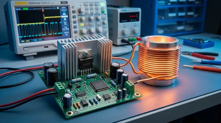
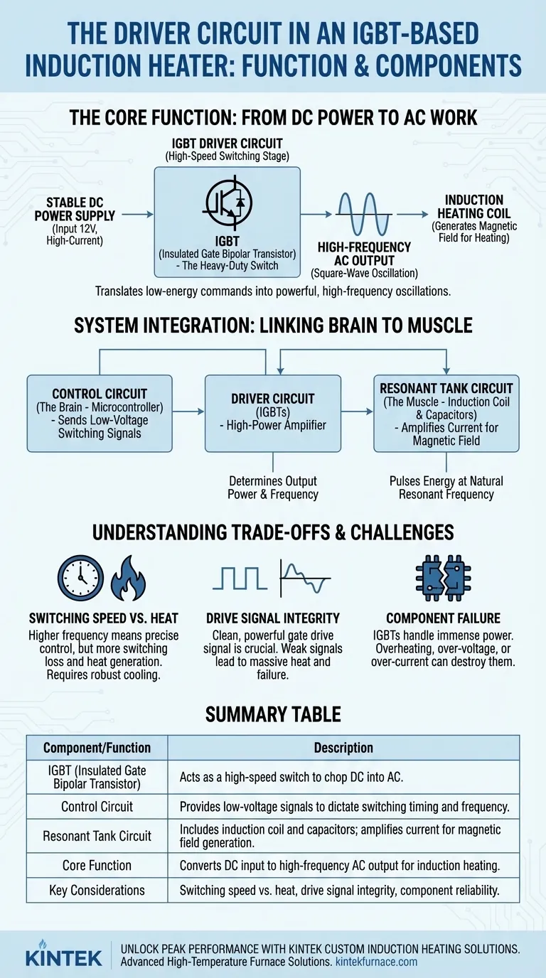
The driver circuit in an IGBT-based induction heater is the high-power switching stage that controls the flow of current to the induction coil. Its primary component is the Insulated Gate Bipolar Transistor (IGBT), which acts as an extremely fast electronic switch. The driver's core function is to take a direct current (DC) input from the power supply and chop it into a high-frequency alternating current (AC) output, which is then fed to the heating coil.
The driver circuit's fundamental purpose is to act as a high-power amplifier. It translates low-energy commands from a control circuit into the powerful, high-frequency oscillations required to generate an intense, work-performing magnetic field in the induction coil.
The Core Function: From DC Power to AC Work
An induction heater cannot operate on the steady DC provided by a power supply. It requires a rapidly changing current to induce eddy currents in the workpiece. The driver circuit is responsible for this critical conversion.
The Input: Stable DC Power
The entire system begins with a power supply, which provides a stable, high-current DC voltage (e.g., 12V). This is the raw energy source for the heating process.
The IGBT as a High-Speed Switch
The IGBT is the heart of the driver circuit. Think of it as a heavy-duty light switch that can be flipped on and off tens of thousands of times per second. When "on," it allows current to flow; when "off," it blocks it.
Generating the High-Frequency Oscillation
By rapidly switching the DC power on and off, the driver circuit effectively creates a square-wave alternating current. This high-frequency AC is the essential ingredient for induction heating.
The Driver's Role in the Complete System
The driver circuit does not operate in isolation. It is the crucial link between the system's low-power "brain" and its high-power "muscle."
The "Brain": The Control Circuit
A separate control circuit, often using a microcontroller, dictates the operation. It sends low-voltage signals to the driver circuit, telling the IGBTs precisely when and for how long to switch. This control determines the heater's output power and operating frequency.
The "Muscle": The Resonant Tank Circuit
The driver's AC output is fed into a resonant tank circuit, which consists of the induction coil and one or more capacitors. The driver's job is to pulse energy into this tank at its natural resonant frequency. This is like pushing a swing at the perfect moment, causing the current oscillating within the tank to build to extremely high levels, far higher than the power supply could deliver directly. This massive oscillating current in the coil generates the powerful magnetic field needed for heating.
Understanding the Trade-offs
The performance of a driver circuit is governed by key engineering compromises. Understanding them is crucial for troubleshooting and optimization.
Switching Speed vs. Heat
Higher switching frequencies can offer more precise control, but each switching action generates a small amount of waste heat in the IGBT. As frequency increases, this "switching loss" adds up, demanding more robust heat sinking and potentially reducing overall system efficiency.
Drive Signal Integrity
The signal from the control circuit to the IGBT's gate must be clean, sharp, and powerful enough to switch it on and off decisively. A weak or "sloppy" gate drive signal can cause the IGBT to spend too much time in a partially-on state, leading to massive heat generation and rapid failure.
Component Failure
Because they handle immense power in a dynamic state, the IGBTs in the driver circuit are a common point of failure. Overheating, over-voltage spikes, or exceeding their current rating can destroy them instantly.
Making the Right Choice for Your Goal
Your approach to the driver circuit depends on your objective.
- If your primary focus is building a basic heater: Focus on a proven, well-documented design. The relationship between the driver, control circuit, and resonant tank is critical and difficult to perfect without a solid reference.
- If your primary focus is troubleshooting a faulty heater: The driver IGBTs are a primary suspect. Check them for short circuits and use an oscilloscope to verify that a clean, correct drive signal is reaching the IGBT gates.
- If your primary focus is optimizing efficiency: Ensure the driver is switching at the precise resonant frequency of the tank circuit. Mismatched frequencies are a primary source of energy loss and component stress.
By mastering the driver circuit, you control the very heart of the induction heater, unlocking its full potential for performance and reliability.
Summary Table:
| Component/Function | Description |
|---|---|
| IGBT (Insulated Gate Bipolar Transistor) | Acts as a high-speed switch to chop DC into AC. |
| Control Circuit | Provides low-voltage signals to dictate switching timing and frequency. |
| Resonant Tank Circuit | Includes induction coil and capacitors; amplifies current for magnetic field generation. |
| Core Function | Converts DC input to high-frequency AC output for induction heating. |
| Key Considerations | Switching speed vs. heat, drive signal integrity, component reliability. |
Unlock Peak Performance with KINTEK's Custom Induction Heating Solutions
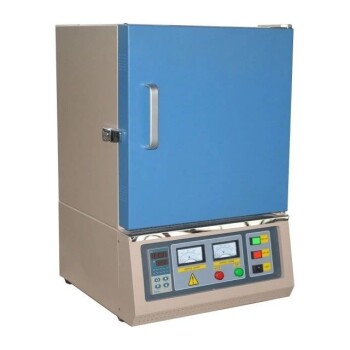
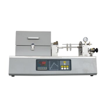
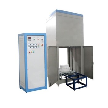
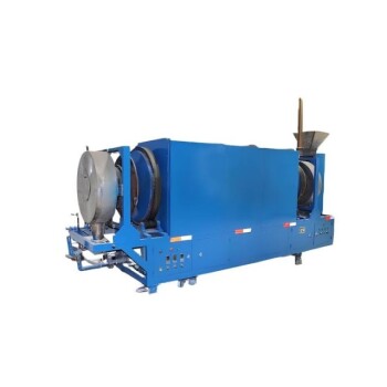
Leveraging exceptional R&D and in-house manufacturing, KINTEK provides diverse laboratories with advanced high-temperature furnace solutions. Our product line, including Muffle, Tube, Rotary Furnaces, Vacuum & Atmosphere Furnaces, and CVD/PECVD Systems, is complemented by our strong deep customization capability to precisely meet unique experimental requirements. Whether you're building, troubleshooting, or optimizing an induction heater, our expertise ensures reliable, efficient performance tailored to your needs.
Contact us today to discuss how we can enhance your laboratory's capabilities with our cutting-edge solutions!
Visual Guide
Related Products
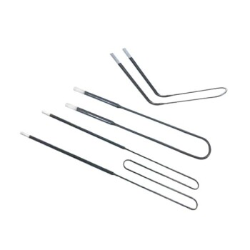
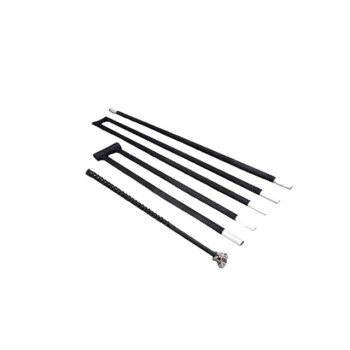
- Molybdenum Disilicide MoSi2 Thermal Heating Elements for Electric Furnace
- Silicon Carbide SiC Thermal Heating Elements for Electric Furnace
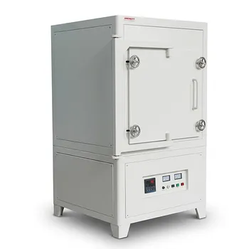
- 1200℃ Controlled Inert Nitrogen Atmosphere Furnace
- 600T Vacuum Induction Hot Press Vacuum Heat Treat and Sintering Furnace
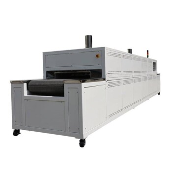
- Mesh Belt Controlled Atmosphere Furnace Inert Nitrogen Atmosphere Furnace
People Also Ask
- What are the key properties and applications of MoSi2 heating elements? Unlock High-Temperature Performance
- What are the typical shapes of MoSi2 heating elements? Explore U, W, L Shapes for Optimal Furnace Performance
- What are the characteristics of molybdenum disilicide heating elements? Unlock High-Temp Performance
- What are the properties of molybdenum disilicide (MoSi2) that make it suitable for high-temperature applications? Discover Its High-Temp Resilience
- What is the service life of MoSi2 heating elements and how do they perform in chemical environments? Maximize Longevity with Proper Use