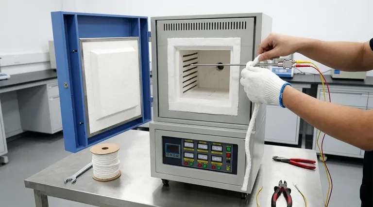
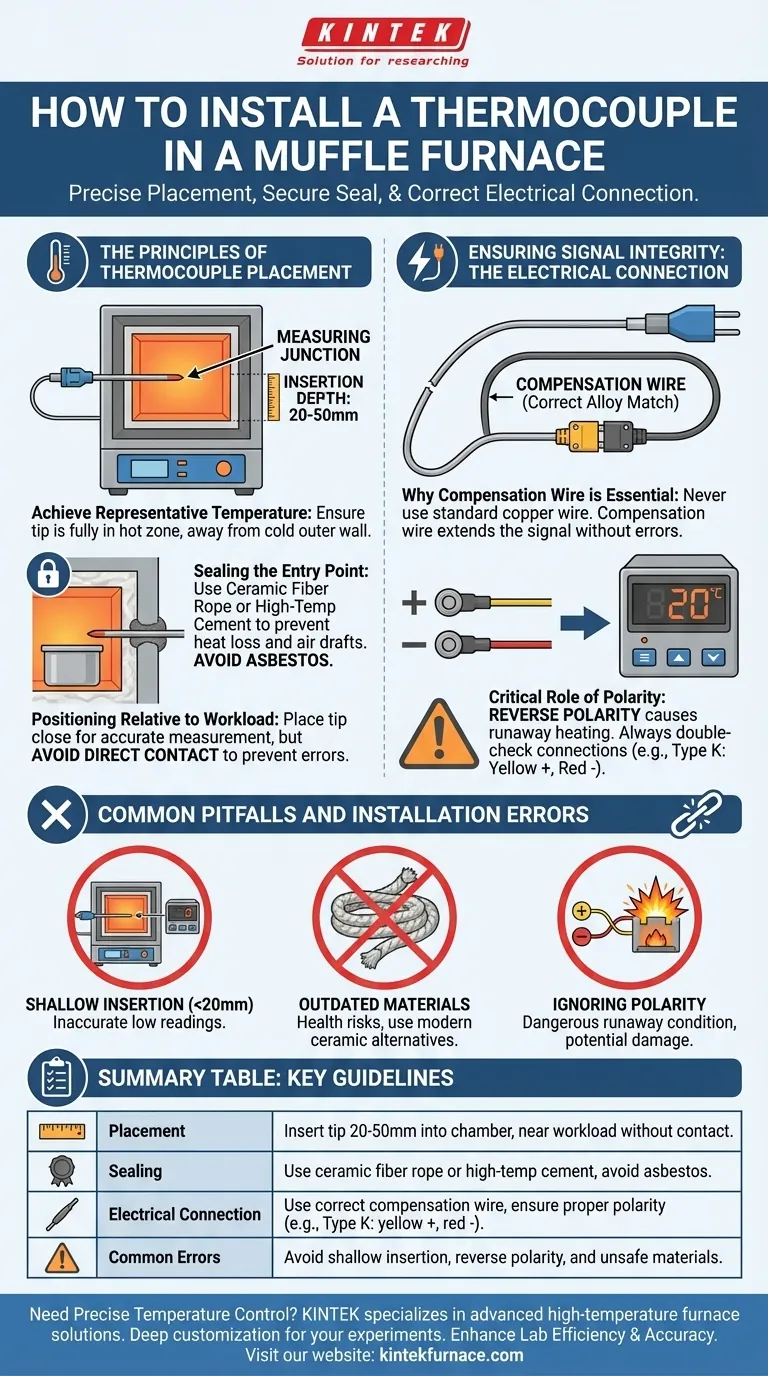
Properly installing a thermocouple in a muffle furnace involves more than just inserting a probe; it requires precise placement, a correct seal, and an electrically sound connection. For a standard installation, the thermocouple tip should be inserted 20-50mm into the furnace chamber. The entry hole must then be sealed, and the probe must be connected to the controller using the correct type of compensation wire with strict attention to polarity.
The goal of thermocouple installation is not just to place the probe, but to ensure the measurement point accurately reflects the true furnace environment and that this signal is transmitted to the controller without error. Every step of the process is about maintaining the integrity of this measurement.
The Principles of Thermocouple Placement
Correct physical placement is the foundation of accurate temperature measurement. The location and depth of the thermocouple tip dictate what temperature is actually being "seen" by your control system.
Achieving a Representative Temperature
The standard insertion depth of 20-50mm is a critical guideline. This ensures the measuring junction (the very tip) is fully inside the hot zone and is not being artificially cooled by proximity to the colder outer wall of the furnace.
If the thermocouple is too shallow, it will read a temperature lower than the actual furnace core, causing the controller to unnecessarily drive more power and overheat your workload.
Sealing the Furnace Entry Point
The gap between the thermocouple sheath and the entry hole in the furnace wall must be sealed. This prevents heat from escaping and, more importantly, stops cool air from being drawn into the furnace, which would create a cold spot around the probe and corrupt the temperature reading.
While older manuals may mention asbestos rope, you must use a modern, safe alternative such as ceramic fiber rope or a high-temperature refractory cement. These materials provide excellent insulation without the significant health risks of asbestos.
Positioning Relative to the Workload
For optimal control, the thermocouple tip should be located near your workload to measure the environment it is actually experiencing. However, it should not touch the workload directly unless you are specifically measuring the material's temperature itself.
Direct contact can lead to measurement errors if the workload has a different emissivity or thermal conductivity than the surrounding air.
Ensuring Signal Integrity: The Electrical Connection
An accurate physical placement is useless if the electrical signal it generates is corrupted. The connection from the thermocouple to the controller is just as critical as the probe's position in the furnace.
Why Compensation Wire is Essential
You cannot use standard copper electrical wire to connect a thermocouple to its controller. Doing so creates new, unintended thermocouple junctions where the copper wire meets the thermocouple alloys, introducing significant and unpredictable temperature errors.
Compensation wire is a special, lower-cost cable made from alloys that have a similar thermoelectric response as the thermocouple itself, but over a more limited temperature range. It effectively "extends" the thermocouple's signal path all the way to the controller's terminals without introducing error.
The Critical Role of Polarity
Thermocouples generate a very small voltage signal that depends on the specific alloys used in their positive (+) and negative (-) legs. Reversing these connections will cause the system to fail catastrophically.
A reverse-connected thermocouple will report a decreasing temperature as the furnace gets hotter. This will cause the controller to apply full power continuously in a runaway condition, potentially destroying the furnace and its contents. Always double-check that the positive and negative terminals on the thermocouple, compensation wire, and controller are all correctly matched.
Common Pitfalls and Installation Errors
Avoiding a few common mistakes is key to a successful and reliable installation.
Using Outdated or Unsafe Materials
Never use asbestos. Always opt for modern ceramic fiber insulation or high-temperature cement for sealing the entry point. It is safer and performs just as well.
Incorrect Insertion Depth
An insertion depth of less than 20mm will almost certainly give you a low and inaccurate reading. Conversely, inserting it too far may interfere with placing your workload or expose the thermocouple to unnecessary mechanical stress.
Ignoring Polarity
This is the most dangerous installation error. Always verify polarity by checking the color codes or markings on the wires and terminals. For Type K, the yellow wire is typically positive (+) and the red wire is negative (-).
Making the Right Choice for Your Goal
Your installation strategy should be guided by your specific requirements for accuracy and control.
- If your primary focus is general reliability: Ensure the thermocouple is inserted at least 20-50mm, seal the entry point with ceramic fiber rope, and double-check that the polarity of your compensation wire is correct all the way to the controller.
- If your primary focus is high-precision control: In addition to the above, carefully position the thermocouple tip as close as possible to your critical workload without touching it, ensuring you are measuring the environment your material is actually in.
Ultimately, a correct thermocouple installation is the foundation for achieving repeatable and trustworthy results from your furnace.
Summary Table:
| Aspect | Key Guidelines |
|---|---|
| Placement | Insert tip 20-50mm into furnace chamber, position near workload without direct contact |
| Sealing | Use ceramic fiber rope or high-temperature cement to seal entry point, avoid asbestos |
| Electrical Connection | Use correct compensation wire, ensure proper polarity (e.g., Type K: yellow +, red -) |
| Common Errors | Avoid shallow insertion, reverse polarity, and unsafe materials for reliable operation |
Need precise temperature control in your lab? KINTEK specializes in advanced high-temperature furnace solutions, including Muffle, Tube, Rotary, Vacuum & Atmosphere Furnaces, and CVD/PECVD Systems. With exceptional R&D and in-house manufacturing, we offer deep customization to meet your unique experimental needs. Contact us today to enhance your lab's efficiency and accuracy!
Visual Guide
Related Products
- 1400℃ Muffle Oven Furnace for Laboratory
- 1700℃ High Temperature Muffle Oven Furnace for Laboratory
- 1800℃ High Temperature Muffle Oven Furnace for Laboratory
- 1200℃ Muffle Oven Furnace for Laboratory
- High Temperature Muffle Oven Furnace for Laboratory Debinding and Pre Sintering
People Also Ask
- How is a laboratory high-temperature muffle furnace utilized in g-C3N4 synthesis? Optimize Your Thermal Polycondensation
- How is a laboratory high-temperature muffle furnace utilized to achieve the specific crystalline structure of LaFeO3 catalysts?
- What role does a muffle furnace play in refractory bricks? Enhance Performance and Durability Testing
- What function does a muffle furnace perform in perovskite formation? Optimize Your Thermal Synthesis
- What is the function of a high-temperature muffle furnace in nano-metakaolin preparation? Master Thermal Activation.